
Views: 145 Author: Site Editor Publish Time: 2026-08-15 Origin: Site


Deploying defective power protection devices carries severe financial and operational consequences. When post-installation failures occur, they lead to equipment damage, immediate safety hazards, and costly product recalls. A reliable voltage protector acts as the primary defense against power anomalies, but its effectiveness relies entirely on the manufacturing quality.
Procurement and engineering teams face a significant challenge in verifying that a manufacturer maintains strict batch consistency across high volumes of protective devices. Without documented proof of performance, buyers risk integrating subpar components into critical electrical networks. A rigorous, documented production testing protocol is the primary differentiator between a high-risk supplier and a reliable manufacturing partner. Understanding standard quality control procedures ensures you select devices capable of protecting your infrastructure.
Comprehensive QA Requires Multi-Stage Testing: Effective production control mandates a combination of mechanical inspection, dielectric withstand testing, contact resistance evaluation, and dynamic functional testing.
Safety-First Environment: High-voltage testing demands rigorous safety protocols, including automated "absence of voltage" verification and shielded test benches to protect equipment and operators.
Phase-Specific Protocols Matter: Testing a three phase voltage protector requires advanced validation for phase sequence, asymmetry, and partial discharge, which are not applicable to single-phase units.
Timing and Calibration are Critical: The reliability of an over under voltage protector hinges on precise trip response times (0-C timing) and auto-recovery delays, requiring automated, calibrated test benches.
Documentation is Non-Negotiable: Validating a manufacturer requires reviewing their Factory Acceptance Testing (FAT) documentation, equipment calibration traceability, and component-level certifications.
Defining success criteria for batch testing requires establishing baseline metrics for production success. Manufacturers must maintain a zero-defect tolerance for safety-critical components. Repeatable trip thresholds and strict adherence to international electrical standards guarantee consistent performance across all production runs. When a facility produces thousands of units daily, statistical sampling is no longer sufficient for safety devices. Every single unit must pass end-of-line testing to verify its operational integrity.
Safety-first test environments are mandatory for high-voltage test and measurement. Facilities utilize calibrated high-voltage probes, isolated test benches, and absence of voltage verification systems to protect testing operators from electrical hazards. Grounding grids and interlocked testing cages ensure that if a device fails catastrophically during a high-potential (hi-pot) test, the operator remains completely isolated from the arc flash or shock hazard.
Analyzing the trade-offs between selecting a vendor with lower upfront costs versus one that invests heavily in automated, end-of-line testing equipment reveals that quality assurance prevents catastrophic field failures. A cheaper unit that bypasses rigorous contact resistance testing might pass a basic continuity check but will overheat and melt under a continuous 63A load. The investment in proper testing infrastructure directly correlates to the lifespan and reliability of the final product.
Standardization across production lines eliminates environmental variables like temperature and humidity that can skew test results. Consistent testing environments ensure every unit meets the same stringent performance criteria before packaging. Climate-controlled testing labs prevent condensation from affecting insulation resistance readings, ensuring the data recorded during the Factory Acceptance Test accurately reflects the device's true capabilities.
Testing Category | Primary Objective | Key Equipment Used | Failure Consequence |
|---|---|---|---|
Mechanical Inspection | Verify physical integrity and assembly | Torque drivers, calipers | Loose connections, physical breakage |
Dielectric Withstand | Confirm insulation strength | Hi-Pot tester | Short circuits, electrical fires |
Functional Timing | Validate trip and recovery speed | Oscilloscope, automated bench | Downstream equipment damage |
Thermal Performance | Ensure stability under load | Thermal cameras, load banks | Overheating, contact welding |
Visual and mechanical inspections serve as the initial QA steps before any voltage is applied to the device. Technicians check the tightness and torque of control and power terminals, verify mechanical interlocks, and assess casing integrity alongside paint and molding quality. A cracked housing or a stripped terminal screw immediately disqualifies a unit from proceeding to electrical testing. Verifying internal components possess required individual certifications before final assembly ensures foundational reliability.
Insulation Resistance (IR) baseline testing utilizes 500V or 1000V DC to ensure a minimum insulation resistance of 100 MΩ. Testing procedures measure from core-to-core and core-to-earth to confirm control signals do not short or leak to ground. This step is non-negotiable because a failure here indicates a fundamental flaw in the internal spacing or a compromised dielectric barrier.
The standard sequence for pre-testing verification follows a strict operational order:
Verify the physical dimensions and housing integrity against the engineering drawings.
Apply specified torque to all external connection terminals to ensure thread strength.
Conduct a dry mechanical cycle of the internal relay to confirm smooth operation.
Perform the baseline 500V DC insulation resistance test across all isolated poles.
Log the initial IR values into the production database tied to the unit's serial number.
Main circuit dielectric withstand testing applies controlled high-voltage AC or DC stress to verify the insulation strength of the assembled unit without causing a breakdown. This hi-pot test pushes the device well beyond its normal operating voltage, typically applying 2kV or more for a specified duration. If the insulation is weak, the tester will detect leakage current exceeding the allowable threshold, and the unit will fail.
Main circuit contact resistance testing utilizes micro-ohm meters to measure the contact resistance of the internal switching mechanism. Low contact resistance prevents localized overheating and voltage drops under maximum load. When a device is rated for 63A, even a fraction of an ohm of excess resistance across the relay contacts will generate significant heat, eventually leading to contact welding or plastic deformation of the housing.
Over/under voltage trip threshold verification simulates single-phase voltage fluctuations. This confirms the single phase voltage protector disconnects the load precisely at the specified upper and lower voltage limits. Programmable AC power sources slowly ramp the voltage up and down, while automated data loggers record the exact voltage at which the internal relay opens. The recorded trip points must fall within a tight tolerance band (e.g., +/- 2V of the setpoint).
Continuous load and thermal performance evaluations test units under maximum rated continuous current to identify potential overheating issues. The devices are placed in a thermal chamber and subjected to their full rated load for several hours. Infrared thermography or attached thermocouples monitor the temperature rise of the terminals and internal components, ensuring they do not exceed the limits defined by safety standards.
Phase sequence and phase loss detection testing simulate missing phases or reversed phase sequences. This ensures the device accurately detects and isolates the fault before downstream motors can run backward or single-phase, which causes rapid overheating and motor failure. The test bench intentionally drops one of the incoming phases or swaps L1 and L2, verifying that the protection relay trips instantly and displays the correct error code.
Asymmetry and imbalance tolerance testing verifies the protector trips when the voltage difference between phases exceeds the configured percentage. In industrial environments, unbalanced loads can cause severe voltage asymmetry, leading to excessive heat in three-phase motors. The testing protocol involves holding two phases at nominal voltage while dropping the third phase's voltage until the asymmetry threshold is breached, confirming the device reacts accurately.
Cross-phase insulation integrity testing evaluates dielectric strength and insulation resistance between individual phase cores. Unlike single-phase units, a three-phase device has multiple high-voltage lines running in close proximity. The hi-pot test must be conducted between L1-L2, L2-L3, and L1-L3 to ensure the internal phase barriers are robust enough to prevent phase-to-phase short circuits during transient overvoltage events.
For high-reliability applications, electrical endurance and transient voltage tolerance testing verifies the protector’s ability to maintain stable operation under repeated switching and abnormal voltage conditions. The device is subjected to repeated overvoltage and undervoltage events, as well as short-duration voltage disturbances, to confirm that its protection functions respond accurately without malfunction or unintended tripping. These tests help ensure reliable and consistent performance in low-voltage three-phase electrical systems.
0-C timing and trip response calibration evaluate reaction times. The device must transition from closed to open within the required milliseconds to protect sensitive downstream equipment. If a massive voltage spike occurs, a delay of even 50 milliseconds can be the difference between safe isolation and destroyed electronics. High-speed oscilloscopes monitor the voltage waveform and the relay contact state to measure the exact reaction time.
Auto-recovery and reconnect delay verification tests the internal timer to confirm the device waits the exact specified duration after voltage normalizes before reconnecting the load. This delay is vital for equipment like compressors, which require time for refrigerant pressures to equalize before restarting. The test bench normalizes the voltage and measures the time it takes for the relay to close, ensuring it matches the user-configured delay setting.
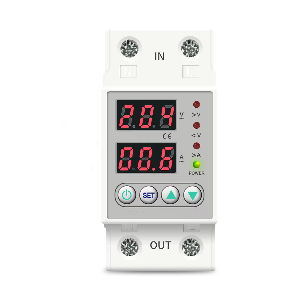
Auxiliary and control circuit validation tests indicator LEDs, digital displays, and auxiliary alarm contacts to ensure accurate status reporting and integration with wider control systems. Technicians verify that the voltage displayed on the device's screen matches the actual voltage supplied by the calibrated test source. Any discrepancy indicates a poorly calibrated internal microcontroller, which would lead to inaccurate protection in the field.
Lab equipment calibration and traceability require ISO-certified calibration records for all high-voltage meters, power sources, and micro-ohm meters. If a manufacturer uses uncalibrated equipment, their test results are meaningless. Procurement teams must request the calibration certificates for the primary test benches to ensure the measurements trace back to recognized national standards.
Automation in production line testing reduces human error, increases throughput, and ensures complete testing coverage rather than relying on random batch sampling. Manual testing is slow and prone to technician fatigue, leading to skipped steps or misread values. Automated test cells connect to the device, run the full suite of electrical and timing tests, and automatically log the results to a central server without human intervention.
Factory Acceptance Testing documentation should include raw test data, pass/fail criteria, and environmental conditions during testing. Procurement teams must review these reports to validate manufacturing claims. A proper FAT report provides a detailed breakdown of the exact trip voltages, reaction times, and contact resistance values for the specific batch of devices being purchased, rather than just a generic "pass" stamp.
Identifying red flags in supplier test reports involves looking for identical test values across multiple units, missing insulation resistance results, or a lack of contact resistance testing. If a FAT report shows exactly 2.10 milliseconds for the trip time on fifty consecutive units, the data is likely falsified. Real-world testing always produces slight variations due to mechanical tolerances.
Aligning factory tests with regional compliance ensures the manufacturer's testing protocols meet specific regulatory requirements of the deployment region. A device tested only to local standards may fail when subjected to the stricter dielectric withstand requirements of international certifications. Ensuring the manufacturer understands and tests to the specific standards required by your jurisdiction prevents costly compliance issues during installation.
The true value of a protective device depends entirely on the rigor of its production testing before deployment. Select manufacturing partners based on their testing automation capabilities and willingness to provide comprehensive documentation.
Request sample test reports to verify quality control claims and check for data variations.
Inquire about equipment calibration schedules to ensure testing accuracy and traceability.
Schedule a virtual or physical factory audit to observe production processes firsthand.
Verify component-level certifications before finalizing procurement agreements.
A: The standard insulation resistance should be a minimum of 100 MΩ when tested with 500V or 1000V DC. This ensures the internal dielectric barriers are intact and prevents leakage current between phases or to ground.
A: Contact resistance testing ensures internal relays do not suffer from localized overheating or voltage drops under maximum load. High resistance across the contacts generates excessive heat, which can melt the housing or weld the contacts closed.
A: Manufacturers use automated test benches and high-speed oscilloscopes to measure the 0-C timing. This ensures the device transitions from closed to open within the specified milliseconds when a voltage anomaly is detected.
A: Three-phase testing requires additional validation for phase sequence, asymmetry, phase loss, and cross-phase insulation integrity. Single-phase testing focuses primarily on simple over/under voltage thresholds and line-to-neutral insulation.
A: It verifies the insulation strength of the assembled unit by applying high-voltage stress without causing a breakdown. This ensures the device can safely handle transient voltage spikes without short-circuiting internally.


