Views: 0 Author: Site Editor Publish Time: 2026-10-10 Origin: Site
Imagine a sudden power outage plunges your facility into darkness. Minutes later, the grid comes back online. However, instead of a smooth transition, it delivers a massive voltage spike. A severe drop immediately follows. In a fraction of a second, expensive household appliances, sensitive electronics, and critical industrial machinery suffer permanent damage. I see this frustratingly common and costly scenario constantly in the field. Power grids are inherently dynamic and unstable systems. Standard miniature circuit breakers are simply not designed to protect against these specific waveform anomalies.
Voltage sags, often called brownouts, and surges act as silent killers of electronic components, refrigerant compressors, and electric motors. The most effective automated solution to mitigate this risk is installing a dedicated protective relay. A proper setup acts as the ultimate gatekeeper for your electrical network. It not only severs the connection during dangerous grid fluctuations but also guarantees a safe, highly reliable power recovery once the utility supply stabilizes. This comprehensive guide explores the mechanics of these devices, how to select the right phase architecture, empirical setup instructions, and practical troubleshooting tactics.
Ultimate Equipment Safety: An automated protective device instantly disconnects your electrical circuit during dangerous high or low voltage events. This prevents thermal runaway and dielectric breakdown in connected appliances.
Smart Power Recovery: Built-in delay timers ensure that electricity is only restored when the grid is completely stable. This specific function is critical for protecting compressor-based appliances like air conditioners and deep freezers from rapid cycling.
Tailored Solutions: Choosing the correct device based on your network architecture is the foundational step to reliable defense. Residential and industrial setups require vastly different hardware.
Straightforward Configuration: Setting up the correct voltage thresholds and recovery delay times is an empirical process. It secures long-term electrical safety when performed according to standard codes.
Electrical equipment is meticulously engineered to operate within a specific voltage tolerance. During an over-voltage surge, extreme electrical pressure overwhelms circuit insulation. This rapid influx of current generates intense heat. It often results in the acrid smell of melted conductive traces, blown capacitors, and catastrophic microprocessor failure. In contrast, an under-voltage event presents a different but equally destructive physical phenomenon. When the voltage drops, inductive loads such as electric motors must draw significantly more current to maintain their required mechanical torque. This exponential current increase causes motor windings to overheat rapidly. Ultimately, this leads to stalled compressors, degraded wire insulation, and eventual electrical fires.
Unlike standard breakers that only trip during massive overcurrent situations or dead short circuits, a voltage monitoring relay continuously samples the incoming Root Mean Square voltage in real-time. It utilizes a precision microcontroller unit to analyze the AC waveform multiple times per second. When the microcontroller detects that the incoming voltage has crossed your pre-programmed upper or lower safety thresholds, it instantly triggers an internal electromagnetic relay. This relay physically breaks the connection between the grid and your load in milliseconds. The device remains in this isolated state while continuously monitoring the grid. It only initiates a recovery countdown when the voltage returns to a safe, nominal range.
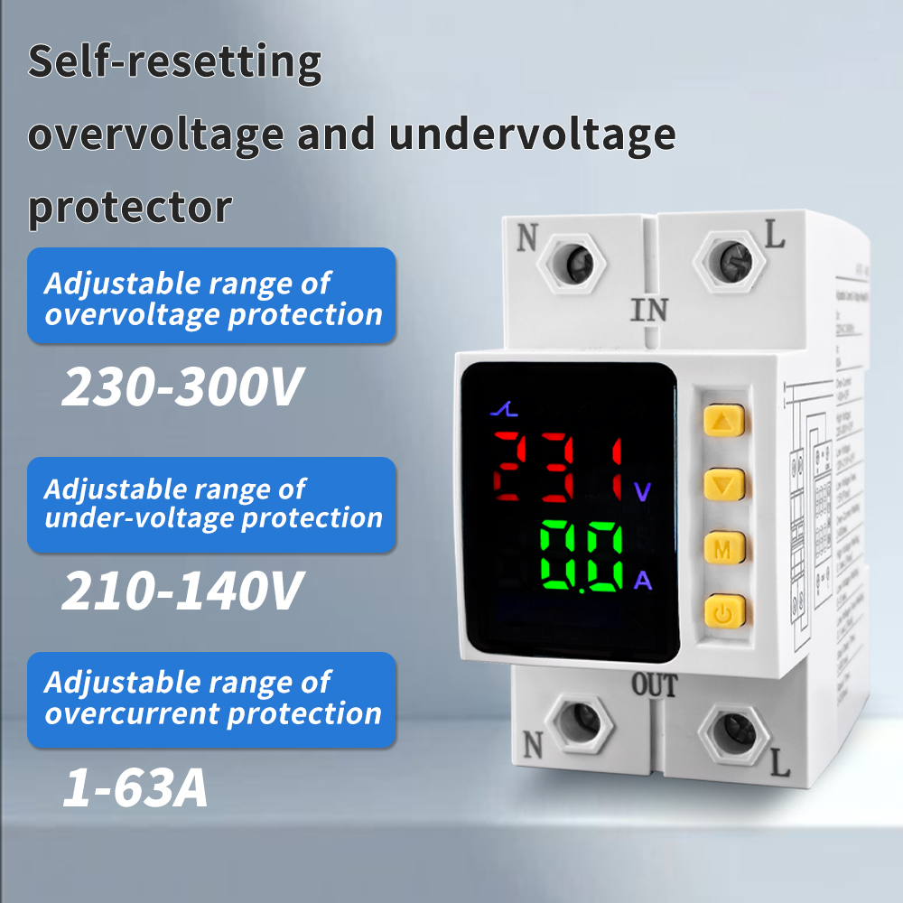
Understanding your specific electrical distribution network is crucial for selecting the appropriate protective hardware. Residential homes, small retail shops, and standard commercial office spaces typically operate on a single-phase electrical system. These networks utilize one active line and one neutral wire. They deliver a nominal voltage of 110V, 120V, 220V, or 230V depending on your region. For these environments, integrating a single phase voltage protector featuring a 63A capacity and a dual-display interface is the exact specification required. Mounted directly after the main isolating switch, it provides comprehensive, whole-house protection for consumer electronics, lighting circuits, and standard HVAC units against local grid instability.
Industrial facilities, large commercial buildings, factories, and agricultural operations require significantly more power to operate heavy machinery. These complex environments utilize a three-phase electrical system. They consist of three distinct alternating currents, typically delivering 380V, 400V, or 480V. In these scenarios, deploying a three phase voltage protector equipped with a six-display interface is an absolute necessity. Beyond standard over and under-voltage monitoring, these advanced units actively scan for phase loss when one line drops completely. They also detect phase unbalance and phase sequence reversal. These secondary diagnostic features ensure that expensive industrial assets, like large induction motors, do not run backward or destroy their mechanical components the moment grid symmetry is compromised.
Feature | Single Phase Models | Three Phase Models |
|---|---|---|
Typical Application | Homes, small offices, apartments | Factories, heavy machinery, industrial chillers |
Voltage Range | 110V to 230V | 380V to 480V and above |
Phase Loss Protection | Not Applicable | Yes, actively monitored |
Wiring Complexity | Simple Line and Neutral | Advanced L1, L2, L3 and Neutral |
The global electrical landscape is undergoing a massive structural transformation. As utility companies rapidly integrate decentralized renewable energy sources like solar and wind, traditional grid inertia decreases. Consequently, industry analysts report a sharp rise in localized grid anomalies. These brief but intense micro-fluctuations in power delivery are wreaking havoc on sensitive microprocessors. Furthermore, extreme weather events are increasingly stressing aging utility infrastructure. This shift has elevated automated voltage regulation from an optional luxury upgrade to a mandatory baseline standard. Today, both residential smart homes and modern industrial facilities rely heavily on automated protective relays. These devices bridge the critical gap between unpredictable utility grids and highly sensitive, expensive modern electronics.
When integrating protective hardware into your distribution board, the amperage rating must correctly align with your network maximum current draw. The capacity defines the maximum continuous current the internal relay contacts can handle without fusing together. A 63A rating is widely considered the industry standard for modern residential and light commercial sub-panels. Installing a 63A over under voltage protector allows you to safely handle approximately 13.8 kW of continuous load on a 220V system. As an empirical rule of electrical safety, this rating should be equal to or slightly greater than the main circuit breaker preceding it.
Older generation analog devices relied on simple indicator lights. This left users guessing about actual grid conditions. High-quality modern units feature integrated digital LED displays that provide real-time telemetry. Dual-display models typically show real-time incoming voltage on one screen and amperage on the other. In contrast, six-display models designed for industrial applications show data for all three independent phases simultaneously. This visibility is invaluable for empirical diagnostics. It allows engineers to troubleshoot grid issues without requiring a handheld multimeter.
Factory-locked parameters offer a rigid approach that rarely suits the nuanced realities of local power grids. A premium device must feature adjustable automatic recovery settings. This programmability allows the electrician to manually define the exact high-voltage cut-off point, the low-voltage cut-off point, and the precise duration of the recovery delay timer. Ultimately, this ensures the device can be tailored to the specific tolerances of the equipment it protects.
Working inside a live electrical distribution box presents a severe risk of arc flash and electrocution. Before beginning any setup procedures, you must completely isolate the panel. Switch the main isolating breaker to the OFF position. Furthermore, implement standard Lockout Tagout procedures if you are in a commercial environment. Once the switch is off, use a calibrated digital multimeter to probe the terminals. Test across Line and Neutral to empirically verify a reading of absolutely zero volts. Never rely solely on the physical position of a breaker switch.
Modern protective relays conform to the IEC 60715 standard. This means they mount seamlessly onto a standard 35mm DIN rail inside your consumer unit. Hook the top lip of the device onto the rail and press firmly until the spring-loaded clip snaps securely into place. For the wiring, strip exactly 12mm of insulation from your correctly sized copper conductors. Insert the incoming Line and Neutral wires from the grid into the respective IN terminals. Next, insert the outgoing wires feeding your sub-breakers into the OUT terminals. Tighten the terminal screws to the manufacturer specified torque rating, typically between 2.5 and 3.0 Nm. This ensures a secure connection that resists thermal expansion.
Once the wiring is secure and the panel cover is safely reinstalled, restore power to the system. Upon receiving power, the device will not immediately supply electricity to the house. Instead, the digital LED screens will illuminate, and an indicator light will flash. This signifies the device is in its initial boot and delay countdown mode. Once the programmed delay time elapses, you will hear a distinct, satisfying mechanical clack as the internal contactor engages. This successfully restores power to your downstream circuits.
Configuring the over-voltage threshold requires balancing appliance safety with the reality of your local grid. Most consumer electronics tolerate a variance of approximately plus 10 percent of their nominal rating. For a standard 220V or 230V system, setting the high-voltage cut-off between 250V and 260V is the standard recommendation. This threshold is high enough to ignore harmless, fleeting fluctuations. However, it is low enough to disconnect the circuit before the voltage causes dielectric breakdown. For 110V or 120V systems, program the limit around 135V to 140V.
Under-voltage configuration is primarily about protecting inductive loads from thermal failure. As voltage drops, motors draw more current, leading to rapid overheating. For a 220V or 230V system, the under-voltage cut-off is typically set between 170V and 180V. Allowing the voltage to drop below 170V significantly increases the risk of a locked-rotor condition in refrigeration compressors. For 110V or 120V systems, the threshold should safely sit around 90V to 95V.
The recovery delay timer is arguably the most critical setting for long-term appliance survival. When a power outage occurs, a refrigeration compressor stops abruptly. This leaves highly pressurized refrigerant gas trapped on one side of the system. If power is restored immediately, the motor will attempt to restart against this massive physical pressure. It will fail to turn, drawing a massive current spike known as Locked Rotor Amps that can melt motor windings. By programming the recovery delay timer to 180 seconds or up to 300 seconds, you provide the refrigerant gases ample time to equalize. When power is finally restored, the compressor starts smoothly under normal mechanical load.
A frequent post-installation observation is the device remaining in the countdown phase indefinitely, refusing to close the relay. In almost all cases, this is not a hardware malfunction. It indicates that the incoming grid voltage is still hovering outside of your programmed safe parameters. To diagnose this, simply look at the digital LED display. If you set your under-voltage limit to 180V, and the display reads 175V, the device is operating exactly as intended. Do not bypass it. Wait for the utility provider to correct the grid.
If your device trips multiple times a day during normal weather conditions, your local grid may have a slightly higher or lower baseline voltage than average. To resolve this nuisance tripping, you can empirically adjust the thresholds. If the over-voltage trips frequently at 245V, observe the peak voltage on the display. If it consistently peaks at 248V but goes no higher, safely adjust your threshold to 255V. Small, incremental adjustments allow you to find the perfect balance between continuous power availability and strict equipment safety.
Modern units utilize specific LED indicators to communicate the exact nature of a fault. A solid red light labeled with OV indicates an Over-Voltage fault. A light labeled with UV indicates an Under-Voltage fault. If your device includes overcurrent protection, an indicator signifies that your household load has exceeded the device maximum amperage rating. Matching the illuminated indicator to the real-time digital readout allows for rapid, accurate diagnostics.
The effectiveness of your electrical defense strategy relies entirely on the build quality of the components you install. When sourcing protective equipment for your distribution network, it is imperative to select a voltage protector manufactured by reputable electrical engineering firms. Look for hardware that carries strict international certifications, including CE and RoHS. These certifications guarantee that the internal relays have been rigorously tested for thousands of switching cycles under heavy loads without failing. This ensures your property is secured when a catastrophic grid failure occurs.
Grid fluctuations are inevitable, but equipment damage is completely preventable. An automated protective relay is a relatively small investment that blocks harmful surges and sags. It potentially saves thousands of dollars in ruined appliances and machinery. Whether your network requires a single-phase unit for a residential property or a complex three-phase unit for an industrial facility, proper installation and accurate delay timer configuration are the ultimate keys to success. Consider upgrading your distribution board today to maintain long-term electrical safety and operational peace of mind. When you are ready to implement a robust electrical defense strategy, explore the professional lineup of protective relays at People Electrical Appliance Group. Visit https://www.peopleelect.com to find the exact hardware specification that matches your project requirements.
A surge protector is designed specifically to defend against microsecond, extremely high-voltage spikes, such as those caused by nearby lightning strikes. A voltage monitoring relay, conversely, disconnects power during sustained periods of high or low voltage originating from the utility grid. For comprehensive electrical safety, installing both devices in your network is highly recommended.
While the physical setup involves relatively simple DIN rail mounting and basic terminal wiring, it requires working directly inside the main electrical panel where lethal voltages are present. Because of the inherent dangers of arc flash and strict local building code requirements, it is always recommended to hire a licensed, certified electrician for the installation.
For general consumer electronics and lighting circuits, a short delay of 10 to 30 seconds is usually sufficient to ensure grid stability. However, if your circuit supplies appliances utilizing a refrigerant compressor cycle, including HVAC units, deep freezers, or refrigerators, a delay of 180 to 300 seconds is strictly necessary. This allows internal mechanical pressures to safely equalize before the motor restarts.
Yes, most high-quality three-phase models include built-in, active protection against phase loss, phase unbalance, and phase sequence reversal. These specific features are mandatory to protect expensive industrial induction motors from running inefficiently, operating in reverse, or suffering catastrophic burnout due to missing electrical phases.
If your device begins making a loud chattering or buzzing noise during operation, the internal electromagnetic contactor may be wearing out. Additionally, if the LED screen flickers erratically or the unit refuses to reconnect power even when the grid voltage is confirmed safe by a multimeter, it is time to replace the unit.
While a protective relay is not a direct energy-saving device, it does prevent electrical waste. By disconnecting power during severe under-voltage events, it stops inductive loads like motors from drawing excessive, inefficient current. This preserves the lifespan of your equipment and prevents the wasted energy associated with stalled, overheating motors.