Views: 0 Author: Site Editor Publish Time: 2026-11-22 Origin: Site
Control coils, specifically Under Voltage Trip (UVT) mechanisms in medium-voltage switches and circuit breakers, act as the last line of defense against catastrophic equipment failure during power anomalies. Specifying an inadequate protection device leads to two costly extremes. Hypersensitivity causes nuisance tripping that halts production lines unexpectedly. Conversely, failure to actuate during a genuine voltage sag results in coil burnout, contactor chatter, and severe downstream motor damage. Selecting the right protection requires moving beyond basic voltage ratings. You must evaluate response latency, diagnostic interfaces, auto-recovery settings, and rigorous pre-commissioning checks. Engineers often overlook the thermal limits of the control circuit itself when designing switchgear layouts. This guide provides a technical framework for evaluating and testing a low voltage protector tailored specifically for control coil circuits.
Define Success via ANSI 27: A reliable low voltage protector must align with ANSI 27 standards, ensuring precise drop-out and pick-up voltage thresholds to prevent unsafe switch operation.
Prioritize Adjustable Time Delays: Fixed-delay protectors are insufficient for industrial control coils; adjustable transient-delay and reconnection settings are mandatory to ride through harmless, momentary voltage sags and ensure grid stability before auto-resetting.
Match Display Tech to Diagnostic Needs: Utilizing a single phase dual display undervoltage protector or a three display overvoltage and undervoltage protector drastically reduces troubleshooting time during fault investigations by providing real-time parameter visibility.
Mandate Rigorous Pre-Commissioning: Bench-testing with a variable voltage supply to verify hysteresis, over/under voltage limits, and release mechanisms is non-negotiable before integrating the protector into the main control circuit.
UVT coils maintain a circuit breaker in the closed position while nominal control voltage is present. They operate on a strict mechanical baseline. An electromagnetic field holds a spring-loaded latch in place against heavy mechanical tension. When the control supply drops below a specified threshold, the magnetic flux collapses. The coil de-energizes instantly. This action releases the mechanical trip mechanism. The breaker then automatically opens to isolate the load.
Continuous operation at marginal voltage levels creates severe vulnerabilities. If the voltage sags but does not trigger a definitive trip, the coil experiences excessive thermal stress. AC coils rely on inductive reactance to limit current flow. When voltage drops, the armature may partially disengage, creating an air gap in the magnetic core. This air gap drastically reduces the coil's impedance. The resulting inrush current bakes the copper windings. The insulation degrades rapidly under these conditions. Replacing a burnt UVT coil requires significant downtime, specialized labor, and often a complete re-certification of the switchgear. DC coils face similar thermal degradation if the mechanical latch fails to seat fully during low-voltage conditions, causing the clearing contacts to remain closed and continuously drawing high pull-in currents.
ANSI 27 establishes the operational framework for undervoltage protection. It mandates constant monitoring requirements for control circuits. The protection device must accurately detect the voltage sag. It should initiate an alarm or trigger the circuit breaker trip only when voltage falls outside the safe operational window. Utility companies and industrial facilities rely on this standard to ensure predictable breaker operation during grid faults.
Configuring dual-stage responses proves highly effective in industrial environments. Early-warning alarms notify operators of minor voltage sags, allowing them to shed non-essential loads manually. Hard circuit breaker trips activate only during critical, sustained drops that threaten equipment integrity. You must coordinate the ANSI 27 relay with downstream overcurrent relays (ANSI 50/51). If a downstream fault causes a localized voltage sag, the overcurrent relay should clear the fault before the undervoltage relay trips the main breaker.
You must differentiate between control circuit protection and main power circuit protection. Control protection safeguards the internal switching mechanisms and the UVT coil itself. Main circuit protection isolates heavy operational loads like motors and transformers. A dedicated monitoring relay ensures the control coil never operates in a brownout state. It acts as a gatekeeper, cutting power to the coil before thermal damage occurs.
Monitor the incoming control voltage continuously at the secondary side of the control power transformer.
Compare the real-time RMS voltage against the programmed ANSI 27 threshold.
Initiate the time-delay sequence if the voltage falls below the dropout point.
Execute the trip command by opening the normally closed (NC) relay contact wired in series with the UVT coil.
Lock out the circuit until the voltage recovers past the hysteresis pickup point.
You must evaluate the balance between equipment safety and operational continuity. Adjustable time-delay settings are absolutely necessary for any industrial application. Setting a delay between 0.1s and 5s prevents nuisance tripping. This delay allows the system to ignore brief grid fluctuations. Heavy motor starting inrushes frequently cause these temporary sags. For example, starting a 200HP compressor can pull the local bus voltage down to 80% of nominal for up to two seconds. If the protection relay trips instantaneously, the plant can never start the compressor.
Assess the auto-recovery and reconnection delay functions carefully. You should set reconnection timers between 10 and 60 seconds. This ensures the grid voltage fully stabilizes before allowing the UVT coil to auto-reset. Proper timer configuration prevents rapid on-off cycling during unstable grid conditions, such as rolling brownouts or severe weather events. Mechanical contacts inside the breaker degrade quickly under rapid cycling conditions. A heavy-duty delay mechanism ensures the breaker remains open until the power supply is genuinely secure.
Examine the precision of drop-out (trip) and pick-up (reset) voltage thresholds. Establish strict guidelines for setting specific upper and lower voltage limits. Base these limits directly on the UVT coil's nameplate tolerances. Sustained overvoltage causes thermal breakdown just as quickly as undervoltage causes a failure to actuate. Overvoltage pushes the coil core into magnetic saturation, generating excessive heat that destroys Class F insulation.
Hysteresis plays a major role in relay stability. It defines the required voltage differential between tripping and resetting. For example, a relay monitoring a 120V AC circuit might trip at 96V (80% of nominal). However, it should not reset until the voltage reaches 108V (90% of nominal). This 12V deadband is the hysteresis. Adequate hysteresis prevents the control coil from rapidly chattering when supply voltage hovers near the trip point. Evaluate the tolerance levels of the chosen voltage protector against the specific operational limits of the connected UVT coil. Precision settings eliminate ambiguity during marginal power events.
Assess physical and electrical compatibility with existing panel layouts. Verify DIN rail mounting dimensions and overall footprint constraints. Panel space is often at a premium in modern switchgear, especially in retrofitted Motor Control Centers (MCCs). You must ensure the relay fits within the low-voltage compartment without obstructing wireways or heat sinks.
Evaluate auxiliary contact configurations, such as Normally Open (NO) and Normally Closed (NC) setups. These contacts must interface with SCADA systems, alarm panels, and the breaker's trip circuit. A standard configuration uses the NC contact to hold the UVT coil energized, while the NO contact wires into a PLC input for remote fault annunciation.
Review the impact of the control power source origin. Determine whether the source originates from the line-side, load-side, or an independent Uninterruptible Power Supply (UPS). The source location directly influences protector reliability during a primary fault. Line-side monitoring detects grid issues immediately, before the main breaker closes. Load-side monitoring reflects the actual voltage reaching the coil but requires the main breaker to be closed to function.
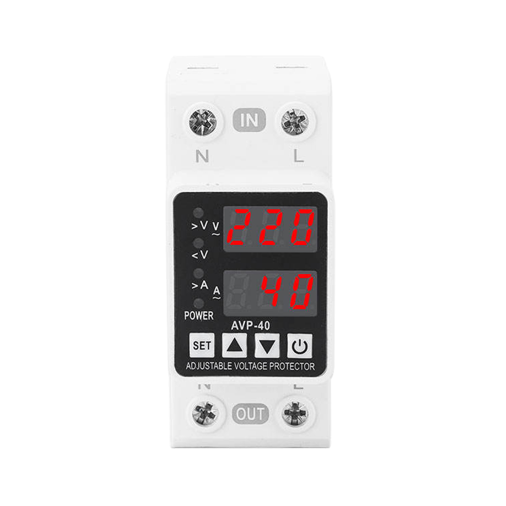
Single-phase control circuits require specific monitoring solutions. A single phase dual display undervoltage protector offers distinct operational advantages. Dual displays provide simultaneous real-time voltage readouts alongside fault codes or set-point values. The top screen typically displays the live RMS voltage, while the bottom screen shows the programmed trip threshold or an active fault code.
This configuration accelerates maintenance response significantly. Technicians can identify the exact fault parameter immediately upon opening the panel door. It eliminates the need for external multimeters during initial fault diagnosis. When a plant goes down at 2 AM, every minute spent probing terminals with a meter costs money. The visual feedback confirms whether the trip resulted from an overvoltage spike or an undervoltage sag. This clarity streamlines the troubleshooting workflow and reduces mean time to repair.
Three-phase control systems demand comprehensive phase-monitoring capabilities. A three display overvoltage and undervoltage protector proves highly effective for these complex setups. It identifies phase imbalance, phase loss, and specific per-phase voltage sags or surges. Phase sequence monitoring is also a standard feature, preventing motors from running backward if utility lines are swapped during maintenance.
You must weigh the trade-off between the increased footprint of multi-display units and the granular diagnostic data they provide. The extra panel space is justified by the depth of real-time operational intelligence gained. Phase asymmetry can destroy three-phase motors rapidly by inducing negative sequence currents that overheat the rotor. Continuous visibility into all three phases ensures operators catch imbalances before they escalate into catastrophic failures. If L2 drops by 15% while L1 and L3 remain stable, the three-display unit highlights the exact phase causing the issue, directing technicians straight to the faulty fuse or loose connection.
Traditional electromechanical or blind solid-state relays offer high durability and low upfront costs. They excel in high-vibration environments or extreme temperature zones where LCD screens might freeze or crack. However, they provide zero diagnostic feedback beyond a simple LED indicator. Technicians must guess the cause of a trip and manually verify voltage levels across all terminals using a True-RMS multimeter.
Modern digital protectors offer precise monitoring, fault logging, and adjustable parameters. Evaluate the overall operational impact. Higher initial investments are offset by reduced downtime through faster fault identification. Assess the cybersecurity and firmware management risks associated with heavily digitized, networked protectors. Balance the need for data against the simplicity of isolated control circuits. A basic digital display provides the perfect middle ground between blind relays and overly complex networked devices. It offers local visibility without requiring IP addresses or network integration.
Protector Type | Ideal Application | Key Diagnostic Feature | Space Requirement | Setup Complexity |
|---|---|---|---|---|
Blind Solid-State Relay | Harsh environments, simple setups | None (LED indicator only) | Minimal (1-2 DIN modules) | Low (Potentiometer dials) |
Single Phase Dual Display | Standard single-phase control circuits | Real-time voltage & fault codes | Moderate (2-3 DIN modules) | Medium (Push-button menus) |
Three Display Protector | 3-Phase systems, phase monitoring | Per-phase voltage, imbalance alerts | Large (3-4 DIN modules) | High (Multi-parameter menus) |
Standard integration follows a strict sequence to ensure proper protection coordination. Power flows from the Grid to the Main Circuit Breaker. It then passes through the voltage monitoring device. Next, it routes to the Residual Current Breaker with Overcurrent (RCBO) or dedicated Control Circuit fuse, finally reaching the UVT Coil.
Improper placement in this hierarchy leads to systemic nuisance tripping or unprotected control segments. If the monitoring relay sits downstream of the control fuse, a blown fuse will register as a total grid failure, triggering unnecessary alarms. Ensure proper breaker coordination and selectivity. A localized control circuit fault or voltage anomaly must isolate only the affected load. This prevents the main facility breaker from tripping and causing widespread outages.
Control Power Transformers (CPTs) require special attention during wiring. If the CPT is undersized, the inrush current of the UVT coil itself can cause a localized voltage sag on the secondary side. The monitoring relay will detect this sag and trip the circuit, creating an endless loop of tripping and resetting. Size the CPT to handle at least 150% of the combined inrush currents of all connected control devices. Keep control wiring separate from high-current power cables to prevent induced voltage errors. Shielded cables or twisted pairs help mitigate electromagnetic interference (EMI) in noisy industrial environments.
Outline a rigorous bench-testing procedure before panel installation. Never install a protection relay straight out of the box without verifying its calibration. Use a variable autotransformer (Variac) or a programmable AC power supply to simulate grid conditions.
Connect the relay to the variable supply and set it to the nominal operating voltage.
Verify the exact drop-out voltage by slowly decreasing the supply voltage in 1V increments while monitoring the output contacts with a continuity tester.
Confirm the pick-up voltage by raising the supply back up, ensuring the hysteresis band matches manufacturer specifications perfectly.
Time the trip delay using a digital oscilloscope or specialized relay tester to ensure it ignores transients shorter than the set point.
Test the auto-reconnection delay by cutting power completely, restoring it, and timing how long it takes for the output contacts to close.
Simulate a sudden total power loss to verify the mechanical latch release speed of the connected UVT coil.
Document all test results to establish a baseline for future maintenance audits. Label the relay with the tested parameters, the technician's initials, and the date of commissioning.
Identify the root causes of control coil chatter. Common culprits include inadequate hysteresis, poor wiring terminations, and severe voltage drop across long control cable runs. When a coil draws its inrush current, a long, undersized wire will cause a localized voltage drop at the coil terminals. This drop can push the voltage below the holding threshold, causing the coil to drop out. Once it drops out, current stops flowing, voltage recovers, and the coil pulls back in. This cycle repeats rapidly, creating a destructive chatter that shatters mechanical linkages.
Implement specific mitigation strategies. Size control cables correctly to minimize voltage drop over long distances. Utilize protectors equipped with definitive, snap-action relay outputs. These heavy-duty outputs prevent partial contact engagement. They ensure the coil either receives full power or none at all. Inspect terminal blocks regularly for loose connections. High-resistance joints exacerbate voltage sags at the coil terminals. Proper torque on all screw terminals is a simple but highly effective preventative measure. Use ferruled wire ends to ensure maximum contact area inside the terminal blocks.
Harmonic distortion also contributes to coil heating. Non-linear loads like Variable Frequency Drives (VFDs) inject harmonics into the control circuit. These high-frequency currents increase eddy current losses in the coil's magnetic core. If your facility operates multiple VFDs, ensure the monitoring relay uses True-RMS sensing rather than peak-sensing to accurately measure the heating potential of the distorted voltage waveform.
Audit existing control coil failure rates to identify recurring voltage anomalies and baseline your facility's power quality.
Define the required ANSI 27 parameters for your specific switchgear based on the manufacturer's thermal damage curves.
Procure sample units for bench-testing drop-out, pick-up, and reconnection thresholds before executing a plant-wide rollout.
Update maintenance protocols to include annual verification of hysteresis settings and terminal torque specifications.
A: The UVT coil is the physical actuator inside the breaker that forces it to trip. The protector is the monitoring relay that detects the voltage drop and cuts power to the UVT coil, or signals it to actuate.
A: Use a variable voltage supply to gradually lower the voltage. Verify the exact drop-out point, time delay, and the subsequent pick-up voltage to ensure proper hysteresis matches the required specifications.
A: Chatter occurs when the supply voltage fluctuates exactly at the coil's operational threshold. A proper protection device with built-in hysteresis prevents this by enforcing a strict gap between trip and reset voltages.
A: Yes, provided it features adjustable time-delay settings. These settings allow the system to ignore harmless, transient voltage dips caused by heavy motor startups or brief grid switching events.
A: It is an adjustable auto-recovery timer. It prevents the device from restoring power to the control coil immediately after voltage returns to normal, ensuring grid stability and preventing rapid on-off cycling.
A: While undervoltage prevents the coil from holding the breaker closed, sustained overvoltage causes excessive current draw and thermal burnout of the coil windings. A comprehensive device monitors both extremes.
A: Response times vary based on system coordination. They typically range from instantaneous (under 50ms) for critical faults to several seconds for coordinated ride-through applications during motor starting.