
Views: 126 Author: Site Editor Publish Time: 2026-08-24 Origin: Site


Industrial energy management, modern grid compliance, and commercial decarbonization rely entirely on the accuracy and integration capabilities of a facility's metering infrastructure. Selecting industrial metering hardware based on surface-level spec sheets often results in protocol mismatches, inaccurate load profiling across L1/L2/L3 phases, and costly integration delays with existing SCADA, Building Management Systems, or solar PV gateways. This guide provides a rigorous technical evaluation framework for analyzing polyphase documentation. We ensure selected hardware meets industrial and utility-grade success criteria for accuracy, physical installation viability, and data interoperability. You need to look past basic marketing claims and dig into the register maps, wiring schematics, and communication protocols. A poorly specified meter will bottleneck your entire energy management system, leading to blind spots in your electrical distribution network. By applying the technical criteria outlined below, facility engineers can confidently specify hardware that integrates seamlessly into complex industrial environments.
Industrial-grade three-phase smart meters require validation of Current Transformer (CT) and Potential Transformer (PT) ratios alongside verified utility-grade accuracy classes (e.g., Class 0.2s or 0.5s).
Integration architecture is a primary failure point; documentation must explicitly detail supported communication protocols (Modbus RTU/TCP, BACnet, DLMS/COSEM, IEC 61850) and register maps.
Facilities incorporating on-site renewables or EV charging infrastructure must specify a bidirectional energy meter to accurately track dynamic active and reactive power import/export.
Deployment strategies must balance heavy-duty three-phase polyphase meters at main incomers with cost-effective, localized single phase WiFi energy meter units for non-critical auxiliary sub-panels.
Evaluating dynamic voltage and current measurements across all three phases (L1, L2, L3) and the neutral line simultaneously establishes a baseline electrical profile. Industrial networks utilize different topologies. You will primarily encounter three-phase three-wire (3CT/2PT) and three-phase four-wire (3CT/3PT) systems. The selected smart energy meter must natively support the specific topology of the switchgear it monitors. Documentation must explicitly state True RMS (Root Mean Square) measurement capabilities. True RMS ensures accurate logging of non-linear loads and harmonic distortion caused by Variable Frequency Drives (VFDs), LED drivers, and heavy motor starting currents. Standard averaging meters fail to capture these anomalies accurately. When reviewing the spec sheet, verify the sampling rate. Higher sampling rates, such as 128 or 256 samples per cycle, provide the granularity needed to detect transient events and short-duration load spikes that trip breakers or damage sensitive control electronics.
Phase measurement goes beyond simple voltage and current. You need to monitor phase angles and sequence. Incorrect phase sequencing during installation can reverse motor rotation, causing immediate mechanical damage. Advanced meters provide real-time phasor diagrams via their web interface or local display. This visual representation allows commissioning engineers to instantly verify correct wiring before energizing the load. Furthermore, neutral current monitoring is non-negotiable in modern facilities. Unbalanced loads and triplen harmonics accumulate in the neutral conductor, potentially exceeding its ampacity rating and causing severe overheating. Your meter must measure and log neutral current to prevent catastrophic thermal failures in the distribution panel.
Understanding the operational and legal differences between accuracy classes dictates hardware selection. Class 1.0 meters offer 1% error margins. They work well for internal cost-allocation and general load monitoring where absolute precision is not legally required. Conversely, Class 0.2s and Class 0.5s meters provide revenue-grade precision. You need this level of accuracy for utility billing compliance, tenant sub-billing, and feed-in tariff verification. Engineers must verify manufacturer calibration certificates and test reports within the product documentation. Look for strict adherence to national and international standards, including the Measuring Instruments Directive (MID), IEC 62053-22, and ANSI C12.20, to guarantee legal metrology compliance.
Accuracy Class | Maximum Error Margin | Typical Application | Required Certification |
|---|---|---|---|
Class 1.0 | 1.0% | Internal sub-metering, basic load profiling | IEC 62053-21 |
Class 0.5s | 0.5% | Commercial tenant billing, light industrial | IEC 62053-22, ANSI C12.20 |
Class 0.2s | 0.2% | Utility main incomers, heavy industrial, grid export | IEC 62053-22, MID |
When evaluating accuracy, consider the performance under varying load conditions. The "s" in Class 0.2s indicates superior accuracy at lower current ranges, often down to 1% of the nominal current. This is vital for facilities with highly variable loads, ensuring accurate measurement during off-peak hours or standby operations. Always request the full calibration report from the manufacturer, not just a generic certificate of conformity. The report should detail the test equipment used, environmental conditions during testing, and the specific error values recorded at different power factors and load percentages.
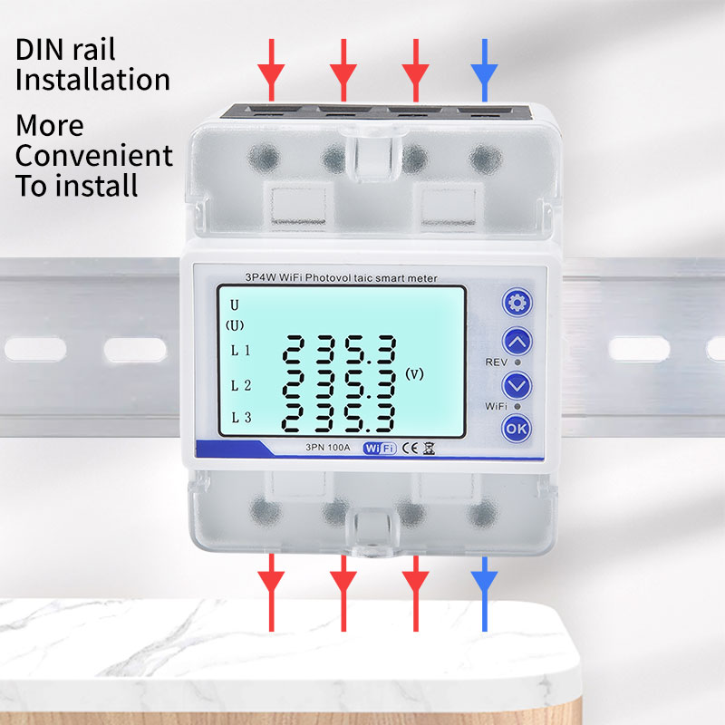
Current thresholds dictate the physical connection method. Direct connect meters handle loads typically up to 65A or 100A. They are ideal for compact installations and localized distribution boards where space is limited. High-voltage, high-current industrial substations require CT/PT operated meters. When reviewing documentation for indirect meters, verify programmable CT/PT transformation ratios. The three phase smart meter must support standard secondary current ratings of 1A or 5A. Additionally, calculate the burden ratings of the current transformers against the meter's input impedance. If the total burden of the wiring and the meter exceeds the CT's rated capacity, magnetic saturation occurs, leading to massive measurement errors and potential equipment damage.
Wiring distance between the CT and the meter plays a significant role in burden calculations. Long cable runs increase resistance, consuming a portion of the CT's VA rating. Always specify appropriate wire gauges based on the distance to minimize voltage drop. For potential transformers (PTs), ensure the meter's voltage input range accommodates the secondary voltage, typically 110V or 120V. The documentation should clearly outline the procedure for programming these ratios via the front panel interface or remote configuration software. Incorrectly programmed ratios are a leading cause of commissioning failures, resulting in readings that are off by factors of 10 or 100.
Physical constraints within electrical panels drive form factor decisions. DIN-rail mounted designs provide modularity and save critical space in constrained sub-panels and modular switchboards. They snap directly onto standard 35mm rails, speeding up installation. Flush-mounted or panel-mounted utility-style meters remain standard for main incomers and large switchgear doors. They offer better visibility for manual inspections and often feature larger, more detailed displays. Thermal management and environmental durability require careful assessment. Evaluate Ingress Protection (IP) ratings based on the installation environment. IP51 ratings suffice for indoor, climate-controlled enclosures. IP65 or IP66 ratings are mandatory for outdoor-rated cabinets exposed to dust, moisture, and direct water jets.
Consider the operating temperature range specified in the manual. Industrial environments often experience extreme temperature fluctuations. A meter installed in an unventilated outdoor kiosk in a desert climate needs a rating up to 70°C. Conversely, installations in cold storage facilities require ratings down to -40°C. Check for conformal coating on the internal printed circuit boards. This protective layer prevents condensation and corrosive gases from short-circuiting the electronics, extending the lifespan of the hardware in harsh chemical plants or wastewater treatment facilities.
Basic kWh accumulation is insufficient for industrial diagnostics. Advanced meters provide registers for Active, Reactive, and Apparent power, alongside Power Factor (PF) per phase. Total Harmonic Distortion (THD) monitoring is essential. Verify if the meter tracks harmonics up to the 31st or 63rd order. High harmonic content overheats transformers, trips breakers prematurely, and degrades motor insulation. Voltage sag and swell logs help diagnose equipment malfunctions and grid instability. Assess the hardware's onboard non-volatile memory capacity. Sufficient local data logging prevents data loss during network outages or disconnects from the Head-End System (HES), ensuring continuous historical records.
Look for waveform capture capabilities. When a voltage sag or transient overvoltage event occurs, the meter should automatically record the waveform for several cycles before and after the event. This high-resolution data allows engineers to pinpoint the exact cause of the disturbance, whether it originated from the utility grid or an internal heavy load switching on. The documentation must detail how to retrieve these waveform files, typically via FTP or a proprietary software tool. Furthermore, check for programmable alarms. The meter should trigger relay outputs or send SNMP traps when specific parameters, such as voltage unbalance or excessive THD, exceed user-defined thresholds.
Facilities utilizing on-site solar PV, Battery Energy Storage Systems (BESS), or regenerative braking systems require specialized metering. A bidirectional energy meter tracks dynamic power flows in both directions. Documentation must outline real-time register configurations for net-metering. This includes separate accumulation registers for imported utility power and exported green energy. You need this separation to prevent billing discrepancies and ensure accurate yield calculations for renewable assets. If the meter only provides a net value, you lose visibility into total consumption and total generation, making performance analysis impossible.
Integration with the solar inverter or BESS controller is a primary concern. The meter often acts as the grid-edge sensor, providing real-time power flow data to the inverter to enable zero-export functions or optimize battery charging schedules. Verify the communication latency. For fast-acting control loops, the meter must update its Modbus registers every 100 to 200 milliseconds. Slower update rates cause the inverter to hunt, leading to unstable grid export and potential utility penalties. The manual should provide a clear wiring diagram showing the RS-485 daisy chain between the meter, the inverter, and the site controller.
Four-quadrant metering isolates and maps inductive versus capacitive reactive power flows across Quadrants I, II, III, and IV. This granular data is vital for industrial sites facing utility penalties for poor power factor. By leveraging real-time four-quadrant data, facility managers can program and trigger automatic capacitor banks or active harmonic filters. This stabilizes the local grid and eliminates reactive power surcharges. Quadrant I represents active power import and inductive reactive power import. Quadrant IV represents active power import and capacitive reactive power export. Understanding these flows allows for precise tuning of compensation equipment.
When reviewing the documentation, check how the meter handles leading and lagging power factors. Some basic meters display a single power factor value without indicating the direction of the reactive power. You need explicit registers for both displacement power factor (fundamental frequency only) and true power factor (including harmonics). This distinction is critical when sizing active harmonic filters. The meter should also provide reactive energy accumulation registers (kvarh) for each quadrant separately, allowing you to audit utility bills and verify the performance of your power factor correction equipment over time.
Not all facility loads require heavy-duty polyphase monitoring. Deploying a single phase WiFi energy meter is highly effective for administrative offices, localized server racks, single-phase HVAC units, and isolated machinery. A rigorous cost-benefit analysis often favors localized wireless sub-meters over running extensive hardwired networks to remote building zones. Pulling conduit and RS-485 cable across a massive warehouse quickly destroys the project budget. Wireless units snap into the local panel and connect to the existing IT infrastructure, drastically reducing installation time and labor costs.
However, technical trade-offs exist. Assess potential wireless signal attenuation caused by reinforced concrete and steel industrial structures. You may need to deploy WiFi repeaters or mesh access points to ensure reliable connectivity. Evaluate network latency and ensure the devices support robust cybersecurity protocols. Prioritize WPA3-Enterprise over standard WPA2 for corporate network integration. The documentation must clearly explain the provisioning process. Can you configure the network settings via a local Bluetooth connection or a mobile app, or does it require a clunky web interface? Fast, secure provisioning is essential when deploying dozens of sub-meters across a facility.
Reliable data transmission dictates system efficacy. RS-485 serial communication running Modbus RTU remains a resilient standard for noisy electrical environments. It handles long cable runs up to 1200 meters and resists electromagnetic interference when properly shielded and terminated. Ethernet-based networks utilizing Modbus TCP/IP, BACnet/IP, or EtherNet/IP offer low-latency integration directly into SCADA and BMS platforms. These protocols allow multiple clients to poll the meter simultaneously, eliminating the master-slave bottleneck of serial networks. Ensure the meter supports at least 10/100 Mbps auto-negotiation and features a robust RJ45 port.
For remote water treatment systems, distributed pumping stations, and wide-area industrial parks, evaluate LPWAN and cellular alternatives. LoRaWAN, NB-IoT, and LTE-M provide long-range connectivity without extensive local IT infrastructure. When reviewing LoRaWAN documentation, check the supported frequency bands (e.g., EU868, US915) and the payload structure. The manufacturer should provide a decoder script to parse the hexadecimal payload into readable engineering units. For cellular meters, verify the supported carriers and the data consumption per month to accurately estimate ongoing connectivity costs.
Software and firmware documentation must reveal native MQTT support, structured JSON/XML payloads, and open RESTful APIs. Proprietary cloud-only platforms introduce severe vendor lock-in risks. If the manufacturer discontinues the cloud service or raises subscription fees, your hardware becomes useless. Verify the hardware possesses local data push capabilities. It should allow integration with independent, on-premise time-series databases like InfluxDB or Prometheus for customized analytics and dashboarding. The ability to define custom MQTT topics and payload formats ensures compatibility with any third-party IoT broker.
Review the API rate limits and authentication methods. The meter should support token-based authentication or API keys rather than basic HTTP authentication. Check if the API allows bidirectional communication. Can you remotely reset the energy registers, update the CT ratios, or trigger a relay output via an API call? Read-only APIs limit your ability to manage the device fleet remotely. The documentation should include comprehensive API documentation with code examples in Python or cURL to accelerate the integration process for your software engineering team.
Physical installation requires strict adherence to wiring diagrams. Technicians must avoid phase-swapping, ensure phase-voltage alignments match CT directions, and secure proper neutral line connections. Common physical commissioning errors include reversed CT polarity, mismatched phase sequencing, and floating grounds. These errors manifest as reading drift, negative power values on active loads, or wildly inaccurate power factor calculations. A systematic commissioning process prevents these issues from corrupting your energy database.
Verify all voltage connections match the corresponding current transformer inputs (L1 voltage to CT1, L2 to CT2, L3 to CT3).
Check the physical orientation of the CTs. The arrow on the CT must point towards the load. Reversed CTs result in negative active power readings.
Confirm the CT shorting blocks are open after installation. Leaving them closed shunts the current away from the meter, resulting in zero current readings.
Measure the voltage across the meter terminals with a calibrated multimeter to ensure it matches the expected system voltage.
Review the real-time phasor diagram on the meter display to confirm phase angles are approximately 120 degrees apart.
Apply a known load and verify the meter registers the expected kW and Amps.
Networked meters represent potential cybersecurity vulnerabilities. They sit on the edge of your operational technology (OT) network and can provide a pivot point for attackers if left unsecured. Evaluate documentation for secure Over-The-Air (OTA) or local serial firmware update procedures. The hardware must support Encrypted Data Transmission, utilizing TLS/SSL for Modbus TCP or SFTP for CSV data exports. Unencrypted protocols expose sensitive energy consumption data and allow man-in-the-middle attacks to manipulate readings or send malicious control commands.
Furthermore, physical write-protect switches are necessary to prevent unauthorized modifications to billing registers and CT/PT ratios. Once the meter is commissioned and sealed by the utility or facility manager, no one should be able to alter the metrology parameters via the network. Check the documentation for Role-Based Access Control (RBAC). The web interface should support multiple user levels, such as an administrator account for configuration and a read-only account for daily monitoring. Default passwords must be forced to change upon initial login to comply with basic cybersecurity hygiene.
Map your facility's electrical distribution topology to determine the exact mix of direct connect and CT-operated meters required.
Select between DIN-rail and panel-mount form factors based on available space within existing switchgear.
Verify required protocol compatibility, ensuring native support for Modbus TCP, BACnet, or MQTT based on your SCADA or BMS architecture.
Request engineering samples from shortlisted vendors to test API endpoints and local database integration before full-scale deployment.
A: A smart meter features real-time data transmission interfaces, multi-tariff scheduling, remote over-the-air configuration, and advanced power quality diagnostics like THD and voltage sags/swells. A standard meter typically only provides simple manual LCD screen readouts for basic kWh accumulation without network connectivity.
A: It is necessary to separately track forward active energy (utility import) and reverse active energy (solar export). This separation is required to claim feed-in tariffs, verify net-metering billing accuracy, and monitor overall inverter performance without data overlap.
A: Yes. Head-End Systems (HES) or localized energy management software can aggregate data from both three-phase main meters and single-phase WiFi sub-meters into a centralized dashboard, provided all devices utilize open APIs or standard protocol conversion gateways.
A: A polyphase meter measures systems utilizing more than one phase, most commonly three-phase in commercial and industrial sectors. They are critical for accurately measuring both balanced and unbalanced loads generated by heavy machinery and large distribution networks.
A: Standard DIN-rail mounting formats are heavily used for compact distribution boards and modular sub-panels. Flush panel-mounted formats are typically deployed on main switchgear doors for easier manual reading and direct access during inspections.


