Views: 0 Author: Site Editor Publish Time: 2026-11-18 Origin: Site
Industrial motors pull up to 600-800% of their full load amperage (FLA) during startup. This massive current draw creates temporary voltage sags across the local bus. These sudden dips often trip poorly configured safety devices, causing unnecessary downtime. Facility managers and electrical engineers face a strict balancing act. You have to protect critical motors from genuine brownouts while preventing nuisance tripping during normal startup sequences. Unplanned downtime destroys operational efficiency. On the flip side, inadequate protection leads to catastrophic motor failure, contactor welding, and expensive rewinding. Modern protection devices solve this problem using precise time-delay configurations, sequential control, and advanced diagnostics. This guide breaks down how to evaluate, specify, and implement the correct low voltage protector. You will learn to ensure reliable motor starts, prevent unintended re-acceleration, and guarantee equipment longevity.
Inrush vs. Fault Differentiation: Effective low voltage protectors utilize adjustable time-delay settings (typically 1 to 15 seconds) to ride through normal startup voltage sags without dropping the control circuit.
Restart Protocols Dictate Safety: Choosing between manual reset (latching relays) and automatic reset depends strictly on the application; auto-restarts require sequential timers and specific grid conditions to prevent grid collapse upon power restoration.
Breaker-Fed Motor Control: Specialized voltage protection is critical to prevent breaker-fed motors from simultaneously re-accelerating after a voltage dip, which can cause cascading facility-wide outages.
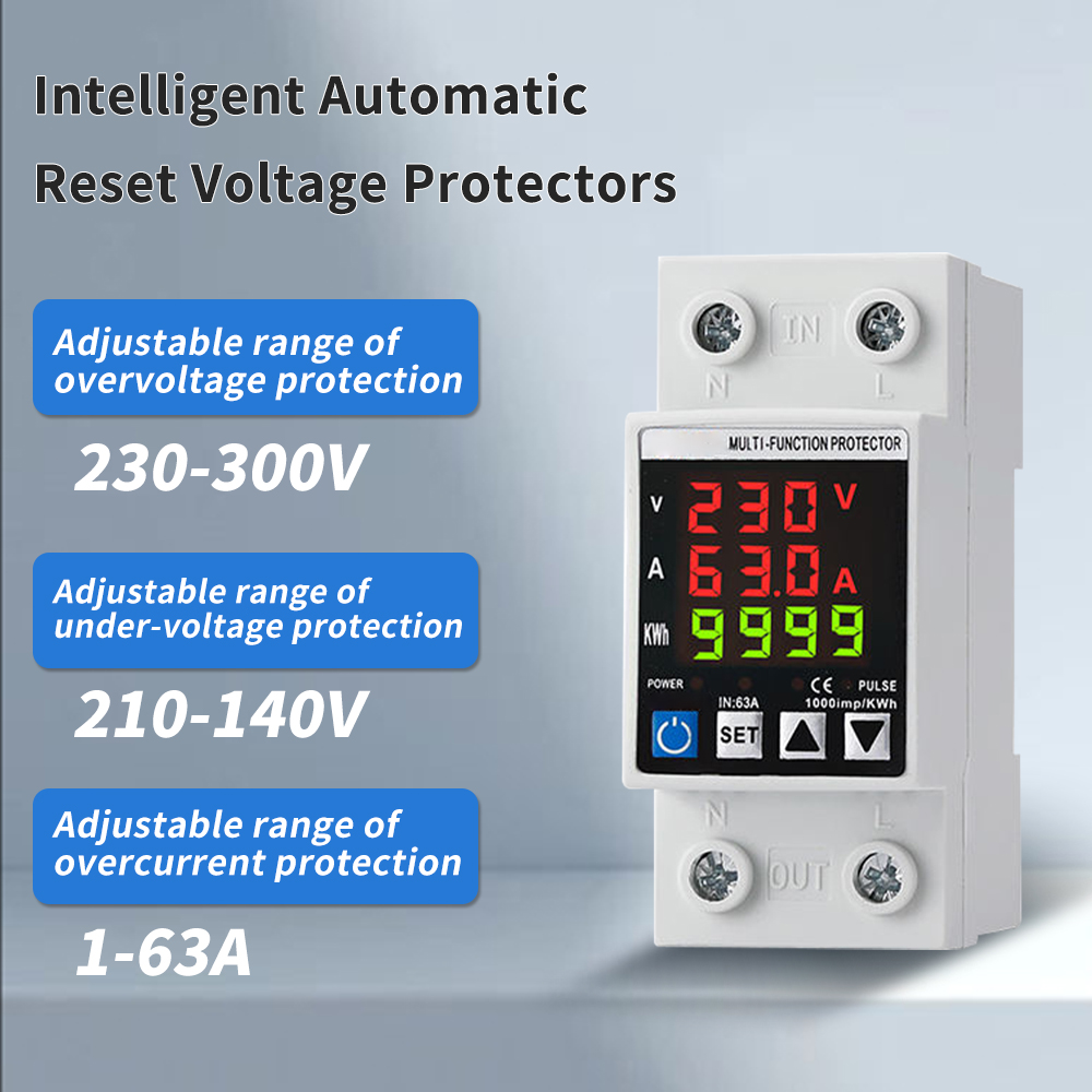
Visibility Accelerates Troubleshooting: Upgrading to a three display overvoltage and undervoltage protector provides real-time phase data, reducing diagnostic time during power quality audits.
System Coordination is Mandatory: A standalone voltage protector must be coordinated with contactor drop-out voltages, thermal overloads, and the broader electrical distribution voltage protector strategy to ensure selective coordination.
Induction motors operate on strict physical principles. Understanding these principles establishes the baseline for why voltage protection is necessary in industrial environments. When you apply power to a stationary motor, it behaves momentarily like a short circuit. The electrical realities of this startup phase demand robust protection strategies to keep the facility running smoothly.
When an induction motor starts, the rotor is at a standstill. Mechanical slip is at 100%. The motor requires massive amounts of reactive power to magnetize the stator and overcome physical inertia. This sudden demand creates locked rotor amps (LRA). LRA typically exceeds normal operating current by six to eight times. This intense current draw pulls heavily on the local electrical grid.
The distribution network struggles to supply this instantaneous reactive power. As a result, the local distribution voltage depresses. You will typically see voltage drops ranging from 10% to 20%. The exact severity depends on upstream transformer impedance and the length of the cable run. Long cable runs with high impedance exacerbate the voltage sag. This temporary dip affects every other piece of equipment connected to the same bus.
Motor Size (HP) | Full Load Amps (FLA) at 480V | Typical Locked Rotor Amps (LRA) | Expected Local Voltage Drop |
|---|---|---|---|
10 HP | 14 A | 84 A | 2% - 5% |
50 HP | 65 A | 390 A | 8% - 12% |
100 HP | 124 A | 744 A | 15% - 20% |
The sequence of events during a standard motor start looks like this:
The contactor coil energizes, pulling the main contacts closed.
Full line voltage hits the stationary stator windings.
The stator draws massive LRA to build the magnetic field.
The rotor begins to turn, generating back-Electromotive Force (back-EMF).
Current draw decreases steadily as the motor approaches synchronous speed.
Induction motors exhibit an inverse relationship between voltage and current. To maintain a constant mechanical torque, the motor must draw more current if the supply voltage drops. As voltage decreases, current increases proportionally. This elevated current generates excessive heat within the motor windings. Heat causes rapid thermal breakdown of the winding insulation through I²R losses. Insulation life drops by 50% for every 10°C rise above its rated temperature limit.
Sustained low voltage also destroys motor starters. This phenomenon is known as "contactor chatter." The magnetic coil inside a motor starter requires a specific minimum voltage to hold the contacts closed. When voltage drops below this threshold, the magnetic field weakens. The spring forces the contacts open. As the load drops, the voltage recovers slightly, pulling the contacts closed again. This cycle repeats rapidly. The contacts arc heavily, generate extreme heat, and eventually weld shut. A welded contactor removes all control from the motor, creating a severe safety hazard.
A standard voltage sag during startup looks identical to a grid brownout in its first few milliseconds. Protection devices must filter out false positives. They rely on internal mechanisms to distinguish between a harmless inrush sag and a destructive utility fault.
Adjustable trip delays serve as the primary filter against nuisance tripping. A standard motor start may take 2 to 5 seconds to reach full speed. High-inertia loads like large fans or centrifuges may take even longer. The protector must ignore voltage drops within this specific acceleration window. If the voltage recovers before the timer expires, the device registers a normal start.
Modern relays utilize different trip characteristics. Definite time delays wait a fixed number of seconds before tripping, regardless of the fault's severity. Inverse time characteristics respond dynamically. If the voltage drops slightly, the relay waits longer. If the voltage collapses completely, the relay trips almost instantly. This dynamic response protects the motor from severe faults while allowing normal inrush sags to clear.
Precise calibration prevents erratic behavior. You must define two distinct thresholds. The "Drop-out voltage" is the exact point where the relay trips and disconnects the load. Engineers typically set this between 80% and 90% of the nominal voltage. For a 480V system, a common drop-out setting is 408V.
The "Pick-up voltage" is the threshold required to allow a restart. This is usually set higher, between 90% and 95% of nominal. The gap between the drop-out and pick-up thresholds is called hysteresis. Hysteresis is mandatory. Without it, a fluctuating grid hovering right at the trip point would cause the relay to rapidly cycle on and off. Hysteresis forces the grid to fully stabilize before the protector allows the motor to run.
Three-phase motors rely on balanced voltage across all lines. An undervoltage condition on a single phase is known as phase loss. Phase loss is significantly deadlier than a balanced three-phase sag. If one phase drops, the remaining two phases draw excessive current to compensate. This creates severe negative sequence currents.
Negative sequence currents generate reverse torque inside the motor. This causes extreme vibration and rapid overheating. Advanced protectors monitor phase asymmetry constantly. They track the voltage differential between L1, L2, and L3 during the start sequence. If the unbalance exceeds a safe threshold (typically 5% to 8%), the relay trips immediately, overriding any time-delay settings.
Selecting the correct device requires matching specifications against operational outcomes. You must evaluate reset capabilities, sequential timing, and diagnostic features to ensure facility safety and uptime.
The choice between manual and automatic resets dictates facility safety protocols. You must match the reset type to the specific machinery.
Manual Restart (Low Voltage Protection - LVP): Manual intervention is required for machinery where unexpected restarts pose severe safety risks. Think of lathes, band saws, or exposed conveyors. During a fault, the contactor releases and opens the seal-in contact. The motor cannot turn back on until an operator physically pushes the start button to re-engage the latch relays. This guarantees that maintenance personnel are not injured by a machine springing to life when grid power returns.
Automatic Restart (Low Voltage Release - LVR): Automatic resets suit unmanned or remote infrastructure. HVAC systems, remote pumping stations, and refrigeration units require LVR. For the control circuitry to automatically restart, three conditions must be met. First, utility voltage must stabilize above the pick-up threshold. Second, the selectable power-on delay timer must fully elapse. Third, no manual lockouts or latched thermal faults can be present in the circuit.
Automatic restarts introduce a massive risk if not managed correctly. When utility power returns after an outage, every motor in the facility will attempt to start simultaneously. This aggregate inrush current will immediately collapse the grid again.
You must implement selectable power-on delays. Assign staggered intervals to different equipment. Set Pump A to restart after 5 seconds, Pump B after 15 seconds, and Pump C after 30 seconds. This sequential control allows the grid to absorb each individual inrush spike before the next motor starts.
Breaker-fed motors are particularly vulnerable. Unlike contactor-controlled motors, breaker-fed motors remain physically connected to the bus during a transient fault. Without sequential control relays, all breaker-fed motors will attempt to re-accelerate at the exact same moment the voltage dip clears. This guarantees a cascading facility-wide outage.
Upgrading from traditional electromechanical relays to digital units offers a massive return on investment. Digital units provide unparalleled visibility into power quality.
A three display overvoltage and undervoltage protector allows maintenance teams to monitor L1, L2, and L3 voltages simultaneously in real-time. You no longer need to open a live panel with a multimeter and full arc-flash PPE to diagnose a fault. This instantly identifies whether a trip was caused by a utility-side sag or a load-side fault.
Furthermore, these units handle sustained overvoltage conditions. Overvoltage lasting minutes or hours degrades motor insulation just as rapidly as undervoltage. High voltage pushes the magnetic core into saturation, generating excessive heat. A digital three-display unit provides comprehensive power quality defense against both extremes.
You must integrate protection devices logically within the broader facility power hierarchy. Placement dictates the level of control and the scope of protection.
Engineers must choose between protecting the entire bus or protecting individual motors. Each approach carries distinct trade-offs.
Protection Strategy | Installation Location | Primary Advantages | Primary Disadvantages |
|---|---|---|---|
Upstream Protection | Main Switchgear / Distribution Board | Protects the entire downstream bus with a single device. Simplifies overall panel wiring and reduces component count. | Lacks granular control. A single utility sag trips the entire facility. Cannot account for individual motor inrush profiles. |
Downstream Protection | Individual Motor Control Center (MCC) Buckets | Highly precise. Allows custom trip curves and time delays for specific high-inertia loads. Isolates faults locally. | Requires more complex wiring and integration into individual motor starter circuits. Takes up more DIN rail space. |
Installing an electrical distribution voltage protector at the main switchgear provides a broad safety net. However, downstream protection at the MCC bucket is mandatory for process motors that require specific ride-through capabilities.
A standalone voltage protector must interface seamlessly with existing automation hardware. Wire the protector's Normally Open (NO) or Normally Closed (NC) auxiliary contacts directly into the motor's start/stop control loop.
When integrating with Programmable Logic Controllers (PLCs), the protector acts as a digital input. The PLC reads the relay state and executes the programmed shutdown sequence. When interfacing with Variable Frequency Drives (VFDs), you must ensure the external relay does not conflict with the drive's internal parameters. Traditional electromechanical contactors simply drop out when the relay opens the control circuit.
Installing protection devices involves practical challenges. Poor commissioning leads to operational headaches and safety violations. You must anticipate and mitigate these risks during installation.
Setting the time delay too short or the voltage threshold too high guarantees failure. The motor will attempt to start, drag the voltage down, and immediately trip its own protection relay. The motor fails to start entirely.
Mitigate this by conducting a thorough power quality study. Capture the exact duration and depth of the inrush sag using a power analyzer. Use this empirical data to set the relay parameters. If the motor takes 4 seconds to accelerate and drops voltage to 82%, set the drop-out threshold to 80% and the time delay to 6 seconds.
Modern VFDs and soft starters feature built-in undervoltage parameters. Installing a standalone voltage protector in front of a VFD creates overlapping conflicts. If a sag occurs, both devices attempt to react. If the external relay trips first, it cuts power to the VFD. You lose all diagnostic fault codes stored in the drive's memory.
Mitigate this by mapping out the protection hierarchy. Ensure the primary device acts first. If the VFD is capable of handling the protection, disable the redundant parameters on the external relay, or adjust the external relay's time delay to act only as a fail-safe backup.
Utilizing auto-reset functions on inappropriate equipment violates safety regulations. OSHA and NFPA 79 standards strictly require manual restarts via seal-in contacts for specific machinery. An unexpected startup on a mechanical press or conveyor belt can cause fatal injuries.
Mitigate this by auditing all motor applications against local electrical codes. Document the safety requirements for every machine. Physically lock out auto-reset capabilities on relays connected to hazardous equipment. Ensure operators understand the manual reset procedures.
A low voltage protector is a highly specific safeguard that must be tuned to the exact inrush profile of the motor it protects. Proper calibration prevents both nuisance trips and catastrophic re-acceleration events. To secure your facility's motor infrastructure, execute the following steps:
Audit your motor control centers to identify high-inertia loads lacking dedicated voltage monitoring.
Log historical inrush voltage sags using a power quality analyzer to establish accurate baseline data.
Specify electromechanical relays with manual resets for machinery requiring operator intervention.
Deploy digital units with staggered auto-resets for unmanned fluid and air handling systems.
A: A low voltage protector handles sustained sags, brownouts, or overvoltages lasting seconds, minutes, or hours. It monitors the steady-state RMS voltage. A surge protector blocks microsecond high-voltage transients and lightning spikes. They serve entirely different protective functions and are often used together in industrial panels.
A: At zero RPM, a motor has no back-Electromotive Force (back-EMF) to oppose the supply voltage. The stator acts almost like a short circuit. The motor requires massive inrush current to magnetize the stator core and overcome the mechanical inertia of the stationary rotor.
A: It depends entirely on the specific motor's acceleration time. Engineers typically set the delay between 2 to 10 seconds. This allows the temporary inrush voltage sag to clear naturally as the motor reaches full speed, preventing the relay from tripping prematurely.
A: As voltage drops, an induction motor draws more current to maintain its mechanical torque. This elevated current causes excessive I²R heating within the windings. This heat degrades the insulation rapidly, leading to internal short circuits and eventual winding burnout.
A: The utility voltage must return and stabilize above the programmed pick-up threshold. The selectable power-on delay timer must fully elapse. Finally, no latched faults or manual lockouts can be present. The application must also comply with safety codes prohibiting unexpected restarts.
A: Breaker-fed motors remain connected to the bus during a transient fault. Without sequential protection, all breaker-fed motors will attempt to re-accelerate simultaneously after a voltage dip clears. This causes a massive aggregate inrush that can trip main breakers and collapse the facility grid.
A: It provides real-time digital readouts for all three phases (L1, L2, L3) simultaneously. This allows maintenance teams to rapidly diagnose phase unbalance, phase loss, or sustained voltage fluctuations without opening live panels or requiring a handheld multimeter.