
Views: 0 Author: Site Editor Publish Time: 2026-09-04 Origin: Site


Traditional single-pole lighting design forces a rigid relationship between a physical switch and an electrical load. This limits your ability to adapt open-plan spaces or multi-zone rooms for different activities. You need to control multiple lighting zones, trigger complex scenes, or manage smart bulbs on entirely different electrical circuits from a single physical access point. Doing this without introducing cloud latency, electrical faults, or extensive rewiring presents a technical challenge. Achieving seamless multi-scene control requires decoupling the physical electrical relay from logical software commands. We will evaluate the hardware configurations, protocol choices, and wiring realities necessary to deploy a Smart Wall Switch for advanced scene management. You will learn how to retrofit an older home or design a new build effectively.
Logical vs. Physical Control: Advanced smart switches allow users to disable the internal electrical relay, maintaining constant power to smart bulbs while using the switch's physical buttons to send digital scene commands.
Protocol Matters for Latency: Local-processing protocols (like Zigbee or Z-Wave) execute multi-device scenes significantly faster and more reliably than cloud-dependent Wi-Fi switches.
Hardware Form Factor Dictates Usability: Dedicated multi-button scene controllers offer intuitive multi-zone management, whereas standard single-paddle switches rely on complex multi-tap programming that can confuse end-users.
Consolidating Wall Clutter: Utilizing virtual grouping via a smart hub often eliminates the need to hire an electrician to physically rewire separate lighting circuits into a single gang box, allowing users to replace multiple "vampire" switches with one unified controller.
A true lighting scene involves more than just turning a bulb on or off. It dictates specific brightness levels, color temperatures, and power states across multiple fixtures simultaneously. When executing a scene, the baseline requirement is zero perceptible latency. Users expect lights to react instantly to a button press. Achieving this requires specific hardware mechanics and a fundamental shift in how we wire lighting circuits.
Decoupling the relay is the primary function for scene control. Field integrators often call this "Smart Bulb Mode." A standard switch physically cuts alternating current (AC) to the light fixture. If you cut power to a smart bulb, it drops off the network. It cannot receive commands. A smart wall switch with relay decoupling solves this problem at the hardware level. When you press the button, the internal electrical relay remains closed. AC power flows continuously to the fixture. Instead of cutting power, the switch sends a digital payload to your smart home hub. The bulbs stay online and ready to react.
Virtual grouping allows you to control lights across different electrical circuits without pulling new Romex through your walls. A central hub acts as the local controller. It intercepts the digital command from the wall switch and broadcasts a state-change command to a predefined group of devices. These devices might sit on different breaker panels. They might even use different communication protocols. The physical wiring no longer dictates logical control. You can group kitchen pendants, under-cabinet strips, and living room lamps into a single scene.
The execution path for a decoupled scene trigger follows a strict sequence:
The user presses the physical button on the wall switch.
The switch firmware registers the press and leaves the internal AC relay closed.
The switch transmits a digital action payload (e.g., "button_1_single_tap") to the local coordinator.
The local hub receives the payload and matches it against a predefined automation rule.
The hub transmits a multicast command to the target group of smart bulbs.
The smart bulbs receive the command and adjust their brightness and color temperature simultaneously.
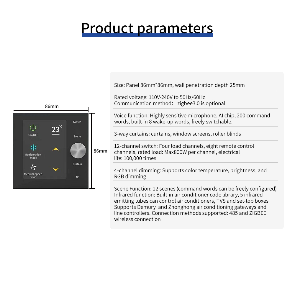
Choosing the right physical interface determines how easily users can trigger multiple scenes. Hardware form factors vary significantly in usability, installation complexity, and daily reliability. You must match the hardware to the specific room requirements.
Dedicated keypad controllers offer the most intuitive multi-zone management. A multi button Zigbee dimmer switch provides discrete physical buttons for specific scenes. You can assign a 4-button or 8-button layout to distinct activities. Button one triggers a "Dining" scene with warm, dimmed lights. Button two triggers an "Entertaining" scene with bright, cool lights. This eliminates guesswork. Users do not need to memorize complex tap sequences. Many of these keypads integrate dimming capabilities directly into the scene presets. You hold the button to ramp the brightness up or down for that specific zone.
You can use standard single-paddle switches to trigger scenes via multi-tap programming. A single tap turns the primary load on or off. A double-tap triggers a "Nightlight" scene. A triple-tap or long-press shuts down the entire house. This approach keeps wall clutter to a minimum and maintains a traditional aesthetic. However, it introduces significant usability trade-offs. Non-standard controls require user training. Visitors will not know that a triple-tap activates the ambient lighting. They will likely mash the button and disrupt the system state.
Wireless remotes offer immense placement flexibility. Devices like Lutron Pico remotes or Zigbee equivalents run on coin-cell batteries. You surface-mount them anywhere on a wall. You can also place them over an existing gang box to simulate a hardwired switch. This approach requires zero interaction with high-voltage wires. It is ideal for adding switches to locations where pulling new wire is impossible, such as brick walls or glass partitions. The primary drawback is battery maintenance, though high-quality remotes last for several years on a single CR2032 battery.
Behind-the-switch relay modules allow you to retain your existing toggle switches. Devices wire directly behind your current hardware. They detect the physical state change of the dumb switch and translate it into a digital scene command. This provides smart scene control without changing the visual hardware of the room. Space inside the junction box is the main constraint. Older homes with shallow boxes rarely accommodate the extra module and the necessary wire nuts.
Integrating voice commands directly at the wall level offers hands-free scene execution. A voice control wall switch features built-in far-field microphones. This eliminates the need for standalone smart speakers cluttering your countertops. You must evaluate the latency and privacy implications of this hardware. Voice-activated scene execution often requires cloud processing. This introduces a slight delay compared to a tactile button press. Ensure the device offers hardware microphone toggles if you install them in bedrooms or private offices.
The underlying communication protocol heavily impacts the reliability and speed of multi-device scene rendering. You must match the protocol to your performance expectations. Relying on the wrong protocol results in delayed lights and frustrated users.
Zigbee operates on a mesh networking topology. Devices route signals through each other, strengthening the network as you add more hardwired nodes. A Zigbee smart dimmer switch excels at scene execution due to a feature called Zigbee Group Messaging. This allows the switch to send a single multicast frame to a predefined group of bulbs. Every bulb in that group receives the command simultaneously. They all change state at the exact same millisecond. This completely eliminates the "popcorn effect," where lights turn on sequentially one after another.
Zigbee also supports direct binding. You can bind a Zigbee switch directly to a Zigbee bulb. If your central hub goes offline, the switch still controls the bulb. The command routes directly from the switch radio to the bulb radio. This provides a massive reliability advantage over cloud-dependent systems.
Wi-Fi switches connect directly to your home router. They often rely on cloud servers to process logic. When you press a Wi-Fi switch to trigger a scene, the command travels to the router, out to an external server, back to the router, and finally to the bulbs. This round-trip introduces noticeable latency. More importantly, it renders the switch useless during internet outages. Wi-Fi devices consume more power and congest your local network if deployed in large numbers. A house with 60 Wi-Fi switches will degrade the performance of your wireless access points.
Robust scene management requires a localized hub. Hubs process scene logic locally, bypassing the cloud entirely. This guarantees instant execution and offline reliability. Proprietary ecosystems guarantee compatibility but limit your hardware choices. Open standards like Z-Wave and Zigbee allow you to mix and match brands. You can pair a switch from one manufacturer with bulbs from another, provided the hub supports both protocols.
Protocol | Network Topology | Local Execution | Scene Latency | Direct Device Binding |
|---|---|---|---|---|
Zigbee | Mesh | Yes (Requires Hub) | Ultra-Low (Multicast) | Yes |
Z-Wave | Mesh | Yes (Requires Hub) | Ultra-Low (Direct Association) | Yes |
Wi-Fi | Star (Router-dependent) | Varies (Often Cloud-dependent) | Moderate to High | No |
Thread | Mesh (IPv6) | Yes (Requires Border Router) | Ultra-Low | Developing |
Physical installation hurdles dictate which hardware you can safely deploy. You must audit your existing wiring before purchasing any components. Failing to understand your electrical topology leads to blown switches and safety hazards.
Most advanced scene-controlling switches require a neutral wire. The internal radio needs constant power to listen for network commands. The neutral wire provides the return path for this continuous current. Older homes built before the 1980s often lack neutral wires in the switch boxes. Electricians used switch loops, bringing only the hot and load wires down to the box.
No-neutral alternatives exist, but they have strict limitations. They leak a small amount of current through the lighting load to stay powered. This requires bypass capacitors to prevent LED bulbs from glowing when turned off. No-neutral switches also typically have strict minimum load requirements. If you try to control a single 5-watt LED bulb with a no-neutral switch, the switch will likely fail to boot or cause severe flickering.
Multi-switch setups control a single lighting load from multiple locations. Traditional 3-way wiring relies on complex traveler wires to alternate the physical current path. When upgrading to smart hardware, you simplify this topology. You hardwire one primary smart switch to control the actual load. At the secondary locations, you tie the line and load wires together to send constant power to the primary switch, and you cap the traveler wires.
You then install wireless auxiliary switches or battery-powered remotes at the secondary locations. These secondary switches send digital commands to the primary switch via the hub. This eliminates the need to decipher confusing traveler wire configurations and ensures the physical relay only actuates from one point.
Many rooms feature a hybrid lighting environment. You might have standard recessed LED cans alongside smart RGB light strips. A multi-button controller handles this perfectly. You wire button one to control the internal physical relay. This switches the AC power for the dumb recessed lights. You configure button two in decoupled mode. It leaves the relay open and sends a digital command to turn on the smart RGB strips. This consolidates physical and digital control into one gang box without requiring separate switches.
Electrical risks arise when using smart dimmers on incompatible LED loads. Ghosting occurs when LED bulbs remain dimly lit even when the switch is off. This happens due to current leakage from the switch radio. Flicker occurs when the dimming curve of the switch does not match the driver in the bulb.
You must verify whether your fixtures require trailing-edge or leading-edge dimming. Leading-edge dimmers (TRIAC) chop the front of the AC sine wave, causing a massive inrush current spike. This destroys delicate LED drivers. Trailing-edge dimmers (MOSFET) cut the AC waveform smoothly before the zero-crossing, reducing inrush current and eliminating buzz. Always specify trailing-edge dimmers for modern LED loads.
Dimming Technology | Component | Waveform Cut | Best Suited For |
|---|---|---|---|
Leading Edge | TRIAC | Front of sine wave | Incandescent, Halogen, Magnetic Transformers |
Trailing Edge | MOSFET / IGBT | End of sine wave | LEDs, Electronic Low Voltage (ELV) Transformers |
Set realistic expectations for deployment. Swapping a standard single-pole switch takes about 15 minutes for a competent DIYer. However, multi-gang retrofits are complex. Opening a 4-gang box reveals a massive nest of hot, neutral, and ground wires. Identifying the correct line and load wires for each circuit requires a multimeter and patience. If you encounter shared neutrals across different breaker phases or lack sufficient box depth, you must hire a licensed electrician to ensure code compliance and safety.
Planning your lighting architecture requires looking beyond the immediate installation. The approach differs significantly based on whether you are building new or retrofitting an existing structure.
During the architectural phase of a new build, you centralize your lighting panels. You run all load wires to a central utility closet. You place low-voltage keypads in the living spaces. This completely eliminates wall clutter. You never look at a bank of six switches again. Retrofitting relies heavily on virtual grouping and micro-modules. You work within the constraints of existing gang boxes. You replace multiple vampire switches with one unified controller and use smart bulbs to handle the individual zoning.
Emerging standards impact hardware investments. Matter is a unifying application layer. Thread is an IPv6-based mesh networking protocol. Together, Matter-over-Thread promises local control and cross-platform compatibility. When selecting hardware for scene control today, consider devices that offer firmware upgrade paths to Matter. This ensures your hardware remains viable as the industry shifts away from fragmented, proprietary ecosystems toward unified local standards.
Achieving seamless multi-scene control requires selecting hardware that supports logical decoupling and local processing. Execute the following steps to deploy your system:
Audit your switch boxes with a multimeter to confirm the presence of neutral wires and measure the internal depth for smart hardware clearance.
Install multi-button keypads in high-traffic areas to provide intuitive, single-press access to complex lighting scenes without relying on multi-tap memorization.
Enable decoupled mode on your switches to maintain continuous power to smart fixtures while retaining physical wall control.
Bind your Zigbee switches directly to your Zigbee bulbs to ensure scene execution remains functional even if your central hub goes offline.
Cap traveler wires in 3-way setups and replace secondary physical switches with battery-powered remotes to simplify your electrical topology.
A: Yes. By using a smart home hub, you decouple the physical relay from the button press. The switch sends a digital command to the hub. The hub then triggers smart bulbs or other switches on entirely different circuits via virtual grouping.
A: If you use local-processing protocols like Zigbee or Z-Wave paired with a local hub, your scenes execute normally without internet access. Wi-Fi switches that rely on cloud servers fail to trigger scenes during an outage.
A: Most advanced scene controllers require a neutral wire to provide continuous power to the internal radio. No-neutral options exist but have strict minimum load requirements and require bypass capacitors to prevent LED flickering.
A: The popcorn effect occurs when lights turn on sequentially. To fix this, use Zigbee devices that support Group Messaging. This allows the hub to send a single multicast command that all grouped bulbs receive and execute simultaneously.
A: Yes. A smart switch physically cuts power to dumb bulbs using its internal relay, just like a traditional switch. You can mix loads on multi-button switches, controlling dumb bulbs with one button and triggering digital scenes with another.
A: Flickering indicates a mismatch between the dimmer type and the LED driver. Modern LEDs require trailing-edge dimming. Ensure your smart switch utilizes a MOSFET trailing-edge dimmer and verify your bulbs are explicitly rated as dimmable.


