
Views: 0 Author: Site Editor Publish Time: 2026-09-05 Origin: Site


Upgrading to smart lighting to gain app and voice control often results in unexpected performance issues. You might experience flickering, buzzing, limited dimming ranges, or lights that refuse to turn off completely. Modern LED fixtures and smart controls operate on fundamentally different electrical principles than legacy incandescent lighting. A Smart Wall Switch requires continuous power for its internal radio. Mismatched dimming protocols inevitably lead to hardware failure or a poor user experience. Successfully specifying a smart dimmer requires moving beyond basic wattage ratings. This guide breaks down how to calculate LED load limits, match dimming protocols, and select the right control hardware to ensure stable, flicker-free performance.
The "Dimmable" Prerequisite: Over 90% of baseline dimming failures can be avoided by ensuring the LED bulb is explicitly rated as dimmable and paired with a modern, LED-rated smart dimmer.
Derating is Mandatory: A smart dimmer’s maximum wattage rating for incandescent bulbs does not apply to LEDs; LED loads typically require a 75% to 90% derating due to inrush current.
Protocol Matching is Critical: Dimming failures frequently stem from pairing Leading Edge (TRIAC) dimmers with Trailing Edge-optimized LED drivers, or mismatching Magnetic Low Voltage (MLV) and Electronic Low Voltage (ELV) systems.
Minimum Load Realities: Low-wattage LED setups often fail to meet the minimum load requirements of no-neutral switches, necessitating the installation of a bypass capacitor.
Wiring Dictates Hardware: The presence or absence of a neutral wire in the switch box is the primary filter for selecting a stable smart dimmer switch.
Solid-state LED drivers and phase-cutting dimmers conflict on a fundamental electrical level. Traditional incandescent bulbs act as simple resistive loads. They dim smoothly as voltage decreases because the tungsten filament simply cools down. LEDs contain complex electronic drivers. These drivers convert high-voltage alternating current into low-voltage direct current. When a dimmer alters the AC waveform, the LED driver must interpret that modified signal. If the driver cannot process the chopped waveform, the lighting circuit becomes highly unstable.
Non-dimmable LEDs lack the internal circuitry required to interpret phase-cut signals. Their drivers utilize basic capacitive droppers or simple switch-mode power supplies designed to expect a full, uninterrupted 120V or 240V AC sine wave. When you connect a non-dimmable bulb to a dimming circuit, the driver attempts to compensate for the missing voltage by pulling more current. This compensation causes the bulb to flicker violently. The internal components quickly overheat, leading to premature failure of the metal-oxide varistors (MOVs) and capacitors. Verifying the "dimmable" certification on the bulb or fixture is the mandatory first step before evaluating switch hardware. Never assume a standard LED can handle a dimmed circuit.
Leading Edge dimming uses a TRIAC component to cut the front edge of the AC waveform. The switch remains off at the start of the AC cycle and suddenly turns on, sending a massive spike of voltage to the bulb. This technology was originally developed for incandescent and halogen lighting. It handles high-wattage resistive loads effectively. However, when applied to capacitive loads like LED drivers, Leading Edge dimming causes massive inrush current spikes. These spikes physically vibrate the magnetic components inside the driver, resulting in audible buzzing from the fixture and premature wear on the switch relay.
Trailing Edge dimming cuts the back edge of the AC waveform using MOSFET or IGBT components. The switch turns on smoothly at the zero-crossing point of the AC wave and turns off later in the cycle. This reverse-phase approach is the preferred standard for modern dimmable LEDs. It provides smoother control, eliminates buzzing, and significantly reduces peak voltage spikes. Trailing Edge dimmers handle the capacitive nature of LED drivers much better than their legacy counterparts.
Feature | Leading Edge (TRIAC) | Trailing Edge (MOSFET) |
|---|---|---|
Waveform Cut | Front edge of the AC sine wave | Back edge of the AC sine wave |
Primary Component | TRIAC (Triode for Alternating Current) | MOSFET or IGBT |
Best Suited For | Incandescent, Halogen, MLV Transformers | Dimmable LEDs, ELV Transformers |
Inrush Current Risk | High (Causes buzzing and relay wear) | Low (Smooth turn-on at zero-crossing) |
You must also differentiate between Magnetic Low Voltage (MLV) and Electronic Low Voltage (ELV) drivers. MLV drivers rely on heavy copper coils to step down voltage and typically require Leading Edge dimmers. ELV drivers use solid-state components and strictly require Trailing Edge dimmers. Mismatching these systems guarantees poor performance, severe flickering, and potential equipment damage.
Traditional mechanical switches simply break the physical copper circuit. Smart switches operate differently. They contain microprocessors, wireless radios, and LED indicator lights. They require continuous electrical power to maintain network connectivity and process commands. This parasitic load means a small amount of current constantly flows through the device.
If the switch lacks a dedicated neutral wire, this operating current must leak through the lighting circuit itself to complete the path to ground. This continuous current draw creates significant problems for highly efficient LEDs. Because LEDs require very little power to illuminate, the leakage current can cause "ghosting." Ghosting occurs when the LEDs glow faintly even after you turn the switch off. Incorrect load matching exacerbates this issue, making proper hardware selection critical for a clean installation.
Achieving stable dimming requires precise mathematical and technical evaluation. You cannot simply match the total LED wattage to the maximum rating printed on the switch box. Proper load calculation prevents relay welding, overheating, and erratic behavior on the lighting circuit.
LED drivers contain input EMI filter capacitors that draw a massive surge of power the moment they turn on. This inrush current lasts only milliseconds, but it can exceed the steady-state operating current by a factor of fifty. A 10W LED fixture might briefly pull 500W of equivalent current. Because of this phenomenon, incandescent ratings are dangerously misleading when applied to LEDs. A switch rated for 400W of incandescent lighting cannot safely handle 400W of LED lighting. If you overload the switch, the combined inrush current will physically weld the internal relay contacts together, permanently ruining the device.
Industry standards dictate a strict derating formula. The general rule of thumb requires derating the switch capacity by 90% for LED loads. Follow these steps to calculate your safe capacity:
Identify the maximum incandescent wattage rating printed on the smart switch.
Multiply that rating by 0.10 to determine the safe LED wattage capacity.
Divide the safe LED capacity by the wattage of a single LED fixture on your circuit.
Round down to the nearest whole number to find the maximum number of fixtures you can safely control.
If a switch has a maximum incandescent rating of 400W, its safe LED capacity is roughly 40W. This means it can safely control a maximum of five 7.1W dimmable LED bulbs, totaling 35.5W. Exceeding this derated capacity risks immediate hardware failure.
Smart dimmers also enforce minimum load thresholds. These thresholds typically range from 10W to 15W. The switch relies on this minimum resistance to stabilize its internal power supply, which is often a small buck converter. Highly efficient LED setups often fall below this threshold. For example, a single 8W downlight fails to meet a 15W minimum requirement.
Falling below the minimum load threshold causes severe operational failures. The switch's internal power supply starves, causing the microcontroller to reboot continuously. You will see the connected LEDs flash on and off every few seconds. The switch will also drop its network connection. You must ensure the total wattage of the lighting circuit exceeds the minimum threshold specified by the manufacturer to maintain a stable power supply.
Controlling multiple LED fixtures on a single circuit introduces additional complexity. Consider a room with six separate downlights, each utilizing its own independent driver. A single smart switch must now manage six separate electrical loads simultaneously. This setup increases the total inrush current exponentially and introduces the risk of voltage drop across long wire runs.
Controlling multiple independent drivers can also cause synchronization issues. Slight manufacturing variances between drivers mean they may respond differently to the same phase-cut signal. One light might dim smoothly while another drops out abruptly or pops on at a different threshold. To mitigate this, always use identical fixtures from the exact same manufacturing batch on a single dimming circuit. Mixing brands or even different generations of the same brand will result in uneven dimming curves.
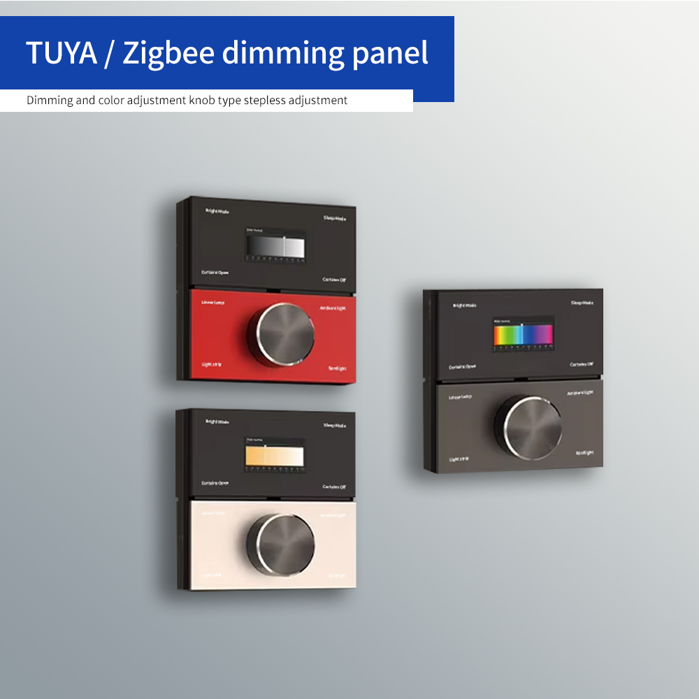
Selecting the right hardware requires evaluating the physical wiring environment and the broader smart home ecosystem. Commercial and high-end residential deployments demand specific technologies to ensure long-term reliability and fast response times.
Neutral-required switches represent the gold standard for LED stability. In this configuration, the switch powers its internal electronics using the hot and neutral wires inside the wall box. It operates completely independently of the lighting load. This separation eliminates leakage current through the bulbs, preventing ghosting and low-end flickering entirely. The switch maintains a rock-solid power supply regardless of what happens on the load side.
No-neutral switches are necessary in older buildings lacking a neutral wire in the switch box. They work by trickling a small amount of current through the connected bulb to complete their own power circuit. Because they rely on the lighting load for power, they are highly sensitive to LED load matching. They frequently struggle with low-wattage setups, cause ghosting, and often require additional hardware installed at the ceiling fixture to function correctly.
Network protocol selection impacts both switch performance and overall network health. Wi-Fi switches connect directly to your router. They are simple to set up for small deployments of three or four devices. However, placing dozens of Wi-Fi switches in a single building clogs the 2.4GHz network bandwidth. They also rely heavily on cloud servers for basic automation tasks, meaning your light schedules fail if your internet goes down.
A Zigbee smart dimmer switch is preferred in dense deployments. Zigbee utilizes a mesh networking protocol. Each hardwired switch acts as a repeater, strengthening the overall network signal and extending range. Zigbee devices consume significantly less power at the switch level, which helps keep internal temperatures low. They also process automations locally through a dedicated hub, ensuring your lights still function instantly during internet outages.
Modern installations often require more than simple up-and-down dimming of a single electrical load. Complex circuits benefit from advanced control interfaces. A multifunction smart wall switch combines traditional dimming capabilities with programmable scene control and sensor inputs. These devices allow you to manage multiple lighting zones, ceiling fans, and automated shades from a single keypad.
Specify a multifunction device when you need to trigger multiple smart bulbs or execute room-wide scenes simultaneously. If you install smart bulbs (like Philips Hue) on a standard switch, cutting the power knocks the bulbs offline. A multifunction keypad can be wired to provide constant power to the smart bulbs while the physical buttons send digital commands over the network. This keeps the network stable, ensures instantaneous response times, and prevents the bulbs from resetting to their default color temperatures.
Even with perfect load calculations, physical installation constraints can introduce performance risks. Understanding practical troubleshooting techniques ensures a successful deployment and prevents costly callbacks to the job site.
When installing no-neutral dimmers with small LED loads, ghosting and flickering are common. The solution is installing a bypass device. A bypass is an encapsulated capacitor that wires in parallel with the lighting load. It is typically installed at the ceiling fixture, connecting across the switched hot and neutral wires.
The bypass provides an alternative path for the switch's operating current. Instead of forcing the leakage current through the sensitive LED driver, the current flows through the capacitor and safely back to the neutral line. You specifically require a bypass when your total LED wattage falls below the dimmer's minimum load threshold. Follow these steps for installation:
Turn off the breaker for the lighting circuit at the main panel.
Access the wiring at the first light fixture in the circuit chain.
Connect one wire of the bypass capacitor to the switched hot wire coming from the dimmer.
Connect the other wire of the bypass capacitor to the neutral wire in the ceiling box.
Secure the connections with wire nuts and carefully tuck the capacitor into the junction box before remounting the fixture.
Smart switches generate heat during operation. The internal electronics and the phase-cutting components must dissipate this thermal energy to prevent failure. Most switches feature metal heat sink tabs on their mounting yokes. When you install multiple switches side-by-side in a multi-gang wall box, you often have to break off these tabs to make the devices fit next to each other.
Removing heat sink tabs reduces the device's ability to cool itself. Consequently, you must apply thermal derating to your load calculations. If you remove one side of tabs, you typically reduce the maximum load capacity by 20%. If you remove both sides, you reduce it by 40%. You must apply this thermal derating before you apply the 90% LED derating rule.
Heat Sink Configuration | Incandescent Capacity (Base 400W) | Safe LED Capacity (After 10% Rule) |
|---|---|---|
All Tabs Intact (Single Gang) | 400 Watts | 40 Watts |
One Side Removed (End of Multi-Gang) | 320 Watts | 32 Watts |
Both Sides Removed (Middle of Multi-Gang) | 240 Watts | 24 Watts |
Never rely on guesswork when pairing hardware. Always cross-reference the manufacturer compatibility lists before procurement. A high-quality smart dimmer switch will have published documentation listing tested and approved LED fixtures. Pay special attention to MLV and ELV specifications on the fixture spec sheets to ensure you match the correct dimming protocol.
If a specific LED driver is not listed on the switch manufacturer's compatibility matrix, test a single unit before buying in bulk. Wire the switch and the fixture on a test bench. Evaluate the dimming range, check for acoustic noise at 50% power, and ensure the light turns off completely without ghosting. Proactive testing prevents massive rework on the job site.
Achieving flawless LED dimming with smart controls is a matter of electrical math, not just software configuration. Prioritize protocol compatibility and load calculation over aesthetic features. To ensure a successful installation, follow these actionable steps:
Audit your existing fixtures to confirm they feature dimmable drivers before purchasing control hardware.
Open your wall boxes to check for neutral wires to determine your hardware constraints.
Calculate your total circuit wattage and apply the 90% derating rule to select a switch with adequate capacity.
Install a bypass capacitor at the fixture level if you must use a no-neutral switch with low-wattage LEDs.
A: Buzzing occurs when you pair a Leading Edge (TRIAC) dimmer with an LED driver designed for Trailing Edge dimming. The incompatible phase-cutting creates high inrush current spikes. These spikes cause the internal magnetic components of the LED driver to vibrate audibly. Switching to a Trailing Edge dimmer usually eliminates this noise.
A: You do not strictly need one, but it is highly recommended. No-neutral dimmers trickle current through the lighting load to power themselves, which often causes flickering or ghosting with low-wattage LEDs. Neutral-required dimmers power themselves independently, providing a much more stable experience.
A: A bypass capacitor provides an alternative path for the leakage current generated by no-neutral smart switches. It prevents this operating current from flowing through the sensitive LED driver. This stops low-wattage bulbs from glowing faintly when the switch is turned off.
A: You must calculate this using the derated capacity rule. Take 10% of the switch's maximum incandescent rating. If the switch is rated for 400W, your maximum safe LED load is 40W. Divide 40W by the wattage of your individual LED bulbs to find the maximum allowed quantity.
A: No. Non-dimmable LEDs lack the internal circuitry required to interpret phase-cut signals. Connecting them to a dimmer will cause severe flickering, overheating, and eventual hardware failure of both the bulb and the switch relay.
A: Flashing at low levels indicates the lighting load has dropped below the dimmer's minimum wattage threshold. It can also mean the driver is incompatible with the dimming protocol. Adjusting the minimum dimming trim level in the switch settings often resolves this issue.


