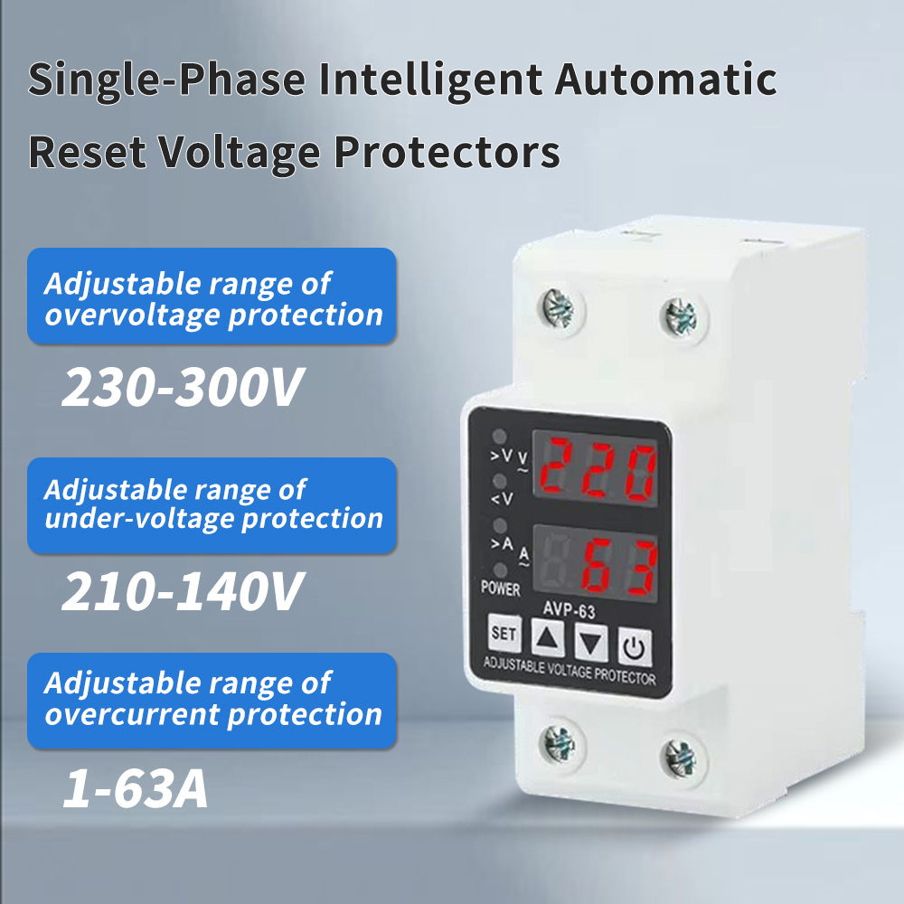
Views: 0 Author: Site Editor Publish Time: 2026-11-20 Origin: Site
Premature equipment failure and intermittent operational faults are frequently misattributed to utility grid instability, masking the true culprit: internal feeder voltage drop. Facility managers and electrical engineers struggle to differentiate between external power sags and internal wiring deficiencies without deploying expensive, temporary power quality analyzers. While primarily designed as a defensive safeguard to protect sensitive loads, a properly specified low voltage protector can serve as a frontline diagnostic indicator, revealing hidden impedance issues within feeder circuits before they cause catastrophic load failure.
Diagnostic Capability: A low voltage protector does not measure wire resistance directly, but its load-dependent tripping behavior provides actionable evidence of excessive feeder voltage drop.
Visibility is Critical: Utilizing a three display overvoltage and undervoltage protector transforms a passive safety device into an active monitoring tool by providing real-time voltage and current correlation.
Configuration Matters: Distinguishing between normal motor inrush current and sustained feeder drop requires precise configuration of undervoltage thresholds, trip delay timers, and auto-recovery settings.
Implementation Limits: While effective for identifying systemic voltage issues, these protectors are supplementary to, not replacements for, formal voltage drop testing (IEEE standards) during commissioning.
Voltage drops occur naturally when electrical current travels through any conductor. Every wire possesses inherent electrical resistance based on its material composition, cross-sectional area, and total length. We calculate this voltage loss using Ohm's Law, where voltage drop equals current multiplied by resistance. Conductor length and wire gauge heavily influence this resistance. Smaller wire gauges present higher resistance per foot. Larger cables offer less resistance. When heavy load current flows through long, undersized wire runs, localized undervoltage conditions develop. This happens entirely independent of the main utility supply. The utility grid might deliver a perfect 480V at the main service entrance. However, the equipment sitting at the end of a 300-foot run might only see 415V under full load.
Equipment suffers directly from this continuous voltage sag. Induction motors face the highest risk on any job site. When supply voltage drops, an induction motor loses magnetic flux. It must draw excess current to maintain its required mechanical torque to keep the load spinning. This excess current generates massive internal heat. Thermal stress rapidly degrades the copper winding insulation. Industry standards dictate that every 10-degree Celsius rise above the rated operating temperature halves the motor's insulation life. Premature motor failure becomes inevitable under these conditions. Bearings dry out from the heat. Windings eventually short circuit. The equipment fails long before reaching its expected mechanical lifespan.
Resistive loads react differently but still suffer performance degradation. Commercial heating elements, incandescent lighting, and industrial ovens experience a massive drop in output when starved of voltage. A 10% drop in supply voltage results in a roughly 19% drop in heat output for a resistive element. This forces heating cycles to run longer, stressing contactors and control relays. While resistive loads do not typically destroy themselves like motors do during a brownout, the resulting operational inefficiency wreaks havoc on production schedules and process control.
Utility-sourced sags behave entirely differently from internal feeder drops. Grid anomalies are typically transient. They last for fractions of a second or a few cycles at most. They affect the entire facility simultaneously. Utility sags occur regardless of your local load state. A lightning strike miles away, a utility capacitor bank switching, or a car hitting a utility pole causes a grid sag. Feeder drop is strictly load-dependent. It remains localized to specific downstream circuits. It only happens when your specific equipment draws heavy power. If the voltage only drops when your compressor kicks on, the utility company is not to blame.
A voltage protector isolates equipment based on these specific voltage anomalies. Its baseline function disconnects the circuit when supply voltage falls below a selected limit. We typically set this limit at 90% of the nominal voltage rating. Circuit breakers respond to overcurrent. They protect the wire insulation from melting and starting a fire. Voltage protectors respond to supply voltage levels. They protect the load from starving. They do not trip on simple overload. This makes them highly targeted diagnostic tools for line impedance. You can frame the device as a continuous monitoring node. It sits at the end of the feeder run and watches for dangerous voltage dips continuously.
Load-correlated tripping signatures reveal the true source of power issues. You must observe the exact moment the device trips to understand the fault. The diagnostic sequence is straightforward for any field technician. First, check the voltage when the machine is idle. If the protector registers normal voltage at idle, the grid is stable and the transformer is tapping correctly. Next, apply the load. If the device trips immediately upon heavy load application, you have an impedance problem. An HVAC compressor startup draws massive inrush current, often five to six times its running load amps. If the voltage crashes during this startup and stays down, it strongly indicates high feeder impedance. The wiring simply cannot handle the current demand. Your internal wiring failed to deliver the required power.
Field technicians follow a specific sequence when using these devices for troubleshooting:
Record the baseline idle voltage at the equipment disconnect.
Verify the protector's undervoltage threshold is set correctly for the specific motor nameplate.
Initiate the equipment startup sequence while monitoring the real-time display.
Note the lowest voltage recorded during the inrush phase.
Observe if the voltage recovers to a normal running level after the motor reaches full speed.
If the protector trips after the delay timer expires, calculate the voltage drop percentage to confirm undersized wiring.
Visibility changes everything in electrical diagnostics. A three display overvoltage and undervoltage protector eliminates diagnostic guesswork. Older legacy devices only had a single red LED to indicate a generic fault. Modern models feature integrated digital displays. They show real-time voltage, current, and fault status simultaneously. You watch the real-time voltage dip exactly as the amperage spikes. This simultaneous data allows technicians to calculate approximate line resistance on the fly. You note the voltage drop. You note the current draw. You divide the voltage drop by the current draw. The result gives you the total circuit resistance. This tells you exactly how degraded the wire run is without needing to pull out a megohmmeter.
Advanced protectors retain historical fault logs. They store the last fault code in their internal memory. They record the exact voltage level at the time of the trip. This provides forensic evidence of intermittent voltage drops. These drops often occur during unmonitored night shifts when facility loads peak. You no longer have to guess why a machine stopped overnight. You arrive in the morning and check the display. The protector tells you exactly how low the voltage fell at 2:00 AM. This data proves the existence of transient load issues. It helps you justify infrastructure upgrades, wire pulls, or transformer adjustments to facility management.
Threshold settings dictate diagnostic accuracy. You must establish a precise undervoltage threshold based on the equipment nameplate. Setting this limit too tight causes constant nuisance tripping. A 95% threshold will trip constantly during normal facility operation. Minor load fluctuations from neighboring equipment will shut down your process. Setting it too loose fails to protect sensitive electronics. An 80% threshold allows dangerous overheating before disconnection. The motor will bake its windings before the protector ever intervenes. You must find the optimal balance based on equipment tolerance. Setting the protector at 90% provides a safe backstop for equipment survival while allowing for normal minor grid fluctuations.
Auto-recovery functions restore power automatically without human intervention. The device reconnects once the supply voltage returns to a safe, pre-selected range. This eliminates manual resets after temporary sags. Maintenance teams save countless hours walking across massive facilities just to reset a tripped relay. Hysteresis prevents rapid on/off cycling. We call this destructive cycling "chattering." When a load disconnects, the line voltage artificially rebounds. The heavy current draw stops instantly. The voltage shoots back up to normal. Without hysteresis, the protector would immediately reconnect. The load would start again, draw heavy current, and the voltage would drop. The device would trip again. This rapid cycle destroys contactors and burns out motors in minutes. Hysteresis requires the recovery voltage to rise significantly above the trip threshold. If it trips at 108V, it might not reconnect until it sees a stable 115V. This ensures grid stability before restarting the heavy load.
Trip delay timers provide transient immunity. You need adjustable trip delays ranging from 0.1 to 10 seconds. Motors draw massive inrush currents during startup. This temporarily pulls down the local voltage. An instantaneous trip would trigger a false voltage drop diagnosis every single time you tried to start the machine. The machine would never run. The delay timer allows normal inrush currents to pass. You set the timer for 3 seconds. The motor starts. The voltage drops. The timer counts down. If the voltage recovers before 3 seconds, the protector does nothing. If the undervoltage condition sustains beyond the startup phase, the protector trips. This separates normal startup physics from actual wiring faults.
You must choose between single-phase and three-phase monitoring depending on the application. A single phase overvoltage protector works best on dedicated branch circuits. It isolates specific single-phase loads. You use these for commercial refrigeration compressors, lighting control panels, and single-phase submersible pumps. Three-phase phase-monitoring relays sit on main feeders. They protect large industrial motors and chillers. They reveal unbalanced feeder drops. Asymmetrical loading across the phases causes these imbalances. Degraded neutral connections also cause severe voltage imbalances. Three-phase protectors detect phase loss, phase reversal, and voltage asymmetry. They provide a broader picture of overall feeder health rather than just monitoring a single leg.
Diagnostic tools carry inherent risks of misdiagnosis if you do not understand the physical environment. You must avoid false positives. A loose termination creates a high-resistance connection. This causes a severe localized voltage drop right at the lug. A systemic feeder length issue also causes a voltage drop along the entire run. A voltage protector will trip in both scenarios. It cannot tell the difference between a loose set screw on a breaker and a wire that is 150 feet too long for its gauge. You must physically inspect terminations before condemning the entire cable run. Grab a calibrated torque screwdriver. Tighten all lugs to the manufacturer's specified torque. Check for signs of thermal discoloration on the busbars or melted wire insulation near the terminals. Rule out bad connections first. Then, you can evaluate the wire gauge and run length.
Thermal cycling causes many of these loose connections. As heavy current flows through a wire, the metal expands. When the load shuts off, the metal cools and contracts. Over months and years, this constant expansion and contraction slowly backs out the terminal screws. Aluminum wire is especially prone to this phenomenon. A protector tripping under load might just be telling you that it is time to perform routine preventative maintenance and re-torque your panels.
Spatial limitations restrict diagnostic visibility. A protector only monitors the voltage at its specific installation point. It cannot reveal voltage drops occurring downstream of its location. If you install the protector at the main breaker panel, it monitors the utility feed and the main transformer. It will not detect a voltage drop at the end of a 200-foot branch circuit feeding a lathe. The machine at the end of the run will still burn up while the protector at the main panel reads a perfect 480V. You must place the protector as close to the sensitive load as possible. Upstream placement protects the main feeder. Downstream placement protects the specific machine. For diagnostic purposes, always install the device at the point of utilization, usually inside the machine's local control panel.
You must know when to escalate your diagnostic efforts. Voltage protectors identify the presence of a problem. They act as a check engine light for your electrical system. They do not provide granular power quality analysis. You must transition to dedicated power quality analyzers for complex issues. Deploy oscilloscopes or Fluke analyzers for harmonic analysis. Use them for exact impedance mapping. If the protector trips constantly despite proper wire sizing and tight lugs, you likely have severe harmonic distortion. Non-linear loads like variable frequency drives, LED lighting arrays, and switching power supplies create harmonics. These harmonics distort the pure sine wave of the voltage. A basic protector cannot diagnose harmonics. It will just trip erratically because the RMS voltage calculation gets skewed by the noise. When the protector points to a problem you cannot see with a standard multimeter, call in heavy testing equipment.
Specifying the right device requires feature-to-outcome mapping. You need specific capabilities for diagnostic utility. Do not buy the cheapest unit available on the shelf. True RMS measurement ensures accurate voltage readings despite waveform distortion. Standard averaging meters read incorrectly when harmonics are present, leading to false trips. Adjustable delay timers prevent nuisance tripping during motor starts. Auto-reset configurations reduce maintenance labor and keep remote pumping stations online. Real-time LED or LCD displays provide instant visual feedback for the technician standing in front of the panel.
Feature | Diagnostic Benefit | Operational Outcome |
|---|---|---|
True RMS Measurement | Accurately reads distorted waveforms from VFDs. | Prevents false tripping in noisy electrical environments. |
Adjustable Trip Delay | Ignores normal motor startup inrush currents. | Allows heavy machinery to start without nuisance shutdowns. |
Real-Time Digital Display | Shows exact voltage and current simultaneously. | Enables instant calculation of line resistance. |
Adjustable Hysteresis | Creates a buffer zone for voltage recovery. | Prevents contactor chattering and motor burnout. |
Fault Memory Logging | Retains the last recorded voltage drop level. | Provides forensic evidence for unmonitored shifts. |
Phase Asymmetry Detection | Identifies unbalanced loads across three phases. | Protects three-phase motors from negative sequence currents. |
Scalability matters for facility-wide implementation. DIN-rail footprints allow easy integration into existing control panels. They snap right onto the standard 35mm rail next to your breakers and terminal blocks. You can mount them inside motor control centers without drilling new holes. Standard protectors handle limited amperage directly through their internal relays. They might handle 40A, 63A, or 80A. For high-amperage loads, you must use the protector to pilot a larger external contactor. The protector monitors the voltage. It sends a low-amperage control signal to the contactor coil. The heavy-duty contactor handles the 200A heavy load current. This modular approach allows you to protect any size load, from a small fractional horsepower fan to a massive industrial shredder.
Evaluate the operational return on investment. A comprehensive voltage protector requires a minimal upfront hardware cost and takes an electrician less than an hour to wire into a control circuit. The return on investment is massive. You prevent expensive motor rewinds. A single motor rewind for a 50HP blower can cost thousands of dollars in parts and labor. You reduce diagnostic labor hours. Electricians spend less time chasing ghost problems with multimeters. You eliminate the downtime associated with mysterious equipment failures. Production keeps running. The device pays for itself the first time it prevents a motor burnout. It transforms reactive maintenance into proactive monitoring.
Install protectors on historically problematic circuits to establish a baseline of voltage performance under load.
Monitor trip logs during peak facility load times to identify load-correlated sags.
Prioritize devices with real-time metering and highly adjustable delay timers over basic fixed-threshold models.
Use the collected voltage data to justify targeted feeder rewiring or transformer tap adjustments.
Verify all physical terminations and lug torques before committing to expensive cable replacements.
A: The standard trip threshold is typically set at 90% of the nominal supply voltage. This aligns with general equipment tolerance levels. The National Electrical Code recommends a maximum 3% voltage drop for branch circuits, making a 10% allowance a safe backstop to prevent severe motor overheating.
A: Yes. Despite the naming convention, most modern protective relays are combined overvoltage and undervoltage devices. They monitor the continuous RMS voltage and will disconnect the circuit if the supply falls outside either the upper or lower programmed safety limits.
A: You must adjust the trip delay timer. Motors draw heavy inrush current during startup, causing a temporary voltage sag. Setting the delay timer between 1 to 5 seconds allows the protector to ignore this brief sag and only trip if the undervoltage condition sustains.
A: Circuit breakers respond to overcurrent and short circuits to prevent wire damage and fires. Voltage protectors monitor supply voltage levels to protect load equipment from starving or overvoltage. Voltage protectors do not respond to overcurrent conditions.
A: A surge protector suppresses microsecond transient voltage spikes using components like MOVs. A voltage protector monitors sustained RMS voltage levels over seconds or minutes. It physically disconnects the load using a relay when the continuous voltage falls outside safe operating parameters.
A: It depends on the load size. Direct-pass models handle lower amperages (typically up to 63A or 80A) internally without external components. For heavy industrial feeds exceeding these limits, you must use CT-driven models or use the protector to pilot a larger external contactor.
A: Wire gauge has an inverse relationship with voltage drop. Smaller, undersized wires create higher resistance. When heavy current flows through undersized wire, it causes a severe localized voltage drop. This guarantees the protector will trip under load, identifying the inadequate wire sizing.