Views: 0 Author: Site Editor Publish Time: 2026-11-17 Origin: Site
Can an over voltage protector catch a voltage swell before it ends? A brief rise may still affect sensitive equipment. Its response depends on voltage thresholds and trip delays. This guide explains detection limits, timing, and how to choose suitable protection.
A voltage swell is a temporary increase in RMS voltage above its normal level. It can occur when large loads switch off, power systems change operating conditions, or faults affect nearby circuits. The voltage usually returns to its normal range after the disturbance ends.
A sustained overvoltage lasts longer. It may result from incorrect voltage regulation, wiring problems, or a supply fault. Both conditions can expose electrical equipment to excessive voltage. However, their duration and required protection responses may differ.
A brief swell is not defined by one universal duration for every protective device. Power-quality standards classify voltage events using specific magnitude and time ranges. The device manufacturer must also define its own detection and trip behavior. Buyers should avoid assuming that every short voltage rise will trigger a relay.
A voltage swell and a transient surge are different power-quality events. A swell involves an increase in RMS voltage over a measurable period. A transient surge is usually a much faster voltage impulse. It can have a steep rise time and a short duration.
An overvoltage relay usually monitors supply voltage. It compares measured voltage against a preset threshold. If the voltage remains outside the permitted range, the device may disconnect the load. This approach is useful for temporary or sustained voltage deviations.
A surge protective device (SPD) serves a different purpose. It limits fast transient overvoltages by diverting surge energy. It is commonly used against lightning-induced and switching-related impulses. An overvoltage relay should not replace an SPD when transient surge protection is required.
A short voltage rise may affect power supplies, electronic control boards, and communication equipment. Some devices can tolerate limited voltage changes. Others may experience stress when the voltage exceeds their operating limits.
Motors and inverters also require suitable voltage conditions. Excessive voltage can increase insulation stress and affect connected control circuits. The actual impact depends on voltage magnitude, event duration, equipment design, and operating conditions.
Repeated disturbances deserve attention as well. One brief event may not cause immediate failure. However, frequent voltage variations can contribute to equipment stress and unexpected shutdowns. Monitoring power quality helps identify recurring problems before they interrupt production.
Note: A voltage event should be evaluated by both magnitude and duration. A peak voltage reading alone may not describe the full disturbance.
An over voltage protector monitors the incoming supply voltage. Many electronic models use internal voltage-sensing circuits. These circuits measure the supply and compare readings against preset limits.
When voltage rises above the upper threshold, the controller evaluates the event. It may start a timer before operating the relay. If the abnormal condition continues, the relay disconnects the load.
However, not every device uses the same sampling method. Some products specify millisecond-level monitoring. Others provide only general protection descriptions. Buyers should request actual measurement and operating specifications.
The upper-voltage threshold defines when protection should respond. For example, a device may allow users to set a maximum voltage. When measured voltage exceeds this limit, its protection logic becomes active.
A brief swell below this threshold may not trigger any action. The protector can continue supplying power because the measured voltage remains within its permitted range. This behavior may be intentional. It helps prevent unnecessary disconnections during normal supply variations.
Threshold selection should match the local supply and connected equipment. A setting that is too high may leave equipment exposed. A setting that is too low may cause frequent trips. Buyers should check the adjustment range and voltage tolerance before choosing a device.
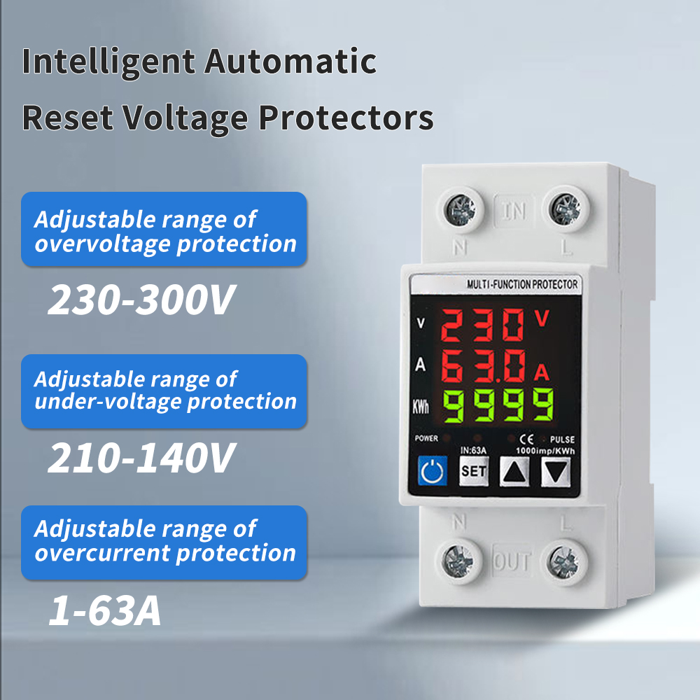
For product selection, review the adjustable overvoltage protection functions. The listed 63A model combines overvoltage, undervoltage, and overcurrent protection. It also provides a color display for voltage and current readings.
The response delay is another important factor. It determines how long an abnormal voltage condition must remain before the protector trips. This delay can help avoid nuisance disconnections caused by brief fluctuations.
Consider a simple example. The voltage rises above the set limit for a very short period. The protector detects the rise and starts its delay timer. If voltage returns to normal before the timer expires, the relay may remain closed.
A longer swell may keep the timer active. The protector can then disconnect the load after the configured delay. Actual behavior depends on the device's control logic and specified response time.
Buyers should distinguish three timing values:
Detection time: How quickly the device identifies abnormal voltage.
Trip delay: How long the abnormal condition must continue.
Disconnection time: How long the relay or switching mechanism takes to open.
Note: A product described as monitoring voltage in milliseconds does not automatically guarantee millisecond-level disconnection. Confirm the complete operating sequence.
The voltage threshold should reflect the supply's normal operating range. It must also protect the equipment connected downstream. These two requirements need careful balance.
Voltage tolerance describes how much variation the device allows around its specified operating point. Measurement accuracy also matters. If the actual voltage is close to the threshold, small measurement differences may affect the trip decision.
For example, two protectors may have the same nominal upper-voltage setting. Yet their measurement accuracy and operating tolerances may differ. One may trip slightly earlier than the other. Buyers should compare technical specifications instead of relying on the displayed setting alone.
A suitable setting also depends on the connected load. Sensitive electronic equipment may require tighter voltage control. Motors and other loads may tolerate different operating ranges. Always follow equipment specifications and local electrical requirements.
Trip delay controls how the protector responds to abnormal voltage. A short delay can improve response to brief swells. However, it may also increase nuisance trips during harmless fluctuations.
Automatic recovery determines when the device reconnects power. Some models wait until voltage returns to a defined normal range. Others include a restart delay to reduce repeated switching.
This function matters in commercial and industrial systems. An immediate restart may affect motors or connected production equipment. A controlled recovery period can help reduce repeated interruptions. The correct setting depends on the load and system design.
Buyers should check whether the delay and recovery settings are adjustable. They should also confirm whether these settings apply to both overvoltage and undervoltage events. Do not assume every model uses identical timing logic.
Measurement accuracy affects whether a brief swell crosses the device's threshold. A protector must measure voltage reliably before it can make a correct trip decision. Poor accuracy can cause delayed or unnecessary operation.
Single-phase systems usually monitor one supply voltage. Three-phase systems require more attention. Each phase may experience different voltage conditions. One phase could rise while the others remain within their normal ranges.
Phase monitoring can help identify imbalance or abnormal phase conditions. Some protectors also monitor phase sequence. These functions are useful for equipment that depends on correct three-phase supply conditions.
For three-phase applications, check whether the device monitors each phase independently. Confirm how it responds when only one phase exceeds the upper limit. Also review whether it disconnects all phases or follows another switching arrangement.
An adjustable over-under voltage protector provides configurable voltage limits. It can disconnect a load when supply voltage exceeds or falls below its permitted range. This function helps protect connected equipment from abnormal supply conditions.
The TX-63A listing describes a 63A adjustable over-under voltage protective device. It identifies automatic disconnection and protection against both overvoltage and undervoltage. The listing also mentions household appliances, industrial machinery, and sensitive electronic devices as applications.
However, the available listing does not clearly state the exact upper-voltage threshold or response time. Buyers should request these values before evaluating its ability to react to brief swells. They should also confirm measurement accuracy and delay adjustment options.
A WiFi voltage protector adds remote monitoring to voltage protection. It can help users check system status without standing beside the distribution panel. Some models also support remote switching or control through an application.
The LIUYI listing describes an 80A WiFi automatic voltage protector. Its listed functions include overvoltage, undervoltage, current limiting, and phase-sequence protection. It also supports DIN rail mounting and remote control of a three-phase switch.
The product listing states a 6 kA breaking capacity. This figure relates to circuit interruption capability under specified fault conditions. It does not indicate how quickly the protector detects a brief voltage swell. Buyers must request separate voltage-response data.
People Electric also lists a smart WiFi single-phase voltage protector. Its published features include adjustable voltage and delay thresholds, three digital indicators, app-based monitoring, and automatic reset. These functions support convenient system supervision.
Rated current describes the current a device is designed to carry under specified conditions. It does not describe voltage detection speed. A 63A protector and an 80A protector may have very different response characteristics.
Breaking capacity is another separate specification. It describes the maximum fault current a protective device can interrupt under defined test conditions. A 6 kA rating cannot prove that a device detects a short voltage swell.
WiFi connectivity also does not guarantee faster protection. It supports remote monitoring and control. The local protection circuit still determines how the device measures voltage and operates its relay.
Buyers should compare the following specifications:
Specification | What It Tells Buyers |
|---|---|
Rated voltage | The intended supply voltage |
Rated current | The current-carrying rating |
Upper-voltage threshold | The voltage level that activates protection |
Measurement accuracy | How closely readings match actual voltage |
Detection time | How quickly abnormal voltage is identified |
Trip delay | How long the condition must continue |
Recovery delay | When power can reconnect |
Breaking capacity | The fault current the device can interrupt |
Tip: Ask suppliers for response-time test results at different voltage levels and event durations. This provides better evidence than current ratings alone.
Start by reviewing the product datasheet. Confirm rated voltage, adjustable upper limits, voltage tolerance, and delay settings. These values show whether the device suits the intended electrical system.
Next, ask for detailed response-time information. A useful specification should explain how the device behaves under different voltage levels. It should also identify the duration required to trigger disconnection.
Do not rely only on phrases such as fast response or high-speed protection. These descriptions lack measurable detail. Request test reports or response curves whenever brief-swell detection is a key purchasing requirement.
A controlled test can show how a protector responds to different voltage events. Qualified technicians can use suitable test equipment to apply defined voltage levels and durations. They can then record whether the device detects the event and disconnects the load.
The test should include several conditions. For example, test voltage rises below the threshold, above the threshold, and at different durations. Record detection behavior, trip timing, and automatic recovery. This helps identify the practical limits of the device.
Testing must follow the manufacturer's instructions and relevant safety requirements. Do not create abnormal voltage conditions on a live production system. Use an appropriate test setup and qualified electrical personnel.
The correct protector depends on the equipment it serves. Electronic control systems may need tighter voltage limits. Motors and inverters may require specific phase and recovery settings.
Check the equipment manufacturer's permitted voltage range. Compare it with the protector's adjustable thresholds and operating tolerances. Also consider the consequences of unexpected power interruption.
Some installations need more than one protection method. An overvoltage relay can disconnect loads during abnormal RMS voltage conditions. An SPD can limit fast transient impulses. Combining suitable devices can provide broader protection when the system design requires it.
First, compare the recorded voltage with the protector's upper limit. If the voltage never exceeds that limit, the device may correctly remain connected. This does not necessarily indicate a product fault.
Next, check the event duration. The voltage may exceed the threshold but return to normal before the trip delay expires. In this case, the protector may detect the event without disconnecting the load.
Also verify the configured voltage range. Incorrect settings can prevent the device from responding as expected. Review the manual before changing any protection parameters.
Check whether the trip delay suits the application. A long delay may allow short swells to pass without disconnection. A very short delay may cause unnecessary trips during normal supply variations.
Compare the protector's displayed readings against an independent power-quality analyzer. This can help identify differences in measurement accuracy. It can also reveal voltage events that the protector's display does not record.
Review the device's wiring and installation conditions as well. Incorrect connections or unsuitable installation can affect operation. Have a qualified electrician inspect the system before making changes.
A voltage protector is designed to protect equipment. It may not provide detailed records of every disturbance. Its display may show current voltage without storing short events.
A dedicated power-quality analyzer can provide more detailed information. Depending on its capabilities, it may record voltage changes, event duration, waveform data, and disturbance timing. This information helps identify the cause of repeated problems.
Monitoring and protection serve different purposes. An analyzer helps users understand what happened. A protective device responds to conditions according to its design. For critical equipment, using both can support better electrical management.
Tip: If unexplained trips or equipment failures continue, record voltage events before changing protection settings. This helps avoid adjustments based on guesswork.
An over voltage protector detects some brief swells. Its response depends on thresholds and trip delays. People Electric offers adjustable voltage protectors with digital displays and WiFi monitoring. These features support safer electrical management and easier system monitoring.
A: Yes, if voltage exceeds its threshold long enough.
A: Detection speed, trip delay, and measurement accuracy matter.
A: It may end before the trip delay expires.
A: No. Use an SPD for fast transient surge protection.
A: Check response-time data and controlled test results.